Introduction
Robot arms built with linear actuators have moved well beyond hobbyist curiosity. Engineers, automation developers, and research teams use them as legitimate prototyping platforms — and for good reason. A linear actuator converts rotary motor motion into controlled straight-line displacement, giving each joint precise, programmable push-pull movement without the complex linkages that rotary servos often require.
The concept is approachable, but consistent, repeatable performance depends on getting four things right simultaneously: component selection, structural design, control electronics, and software.
Weakness in any one of those areas cascades into problems across the others. A perfectly tuned PID loop cannot compensate for an undersized actuator. A correctly rated actuator cannot fix a structurally flawed joint.
This guide covers each area in sequence: initial readiness checks, build steps, performance parameters, common failure modes, and a realistic look at where this approach works — and where it falls short.
Key Takeaways
- Linear actuators drive arm joints through direct rotary-to-linear conversion, producing measurable, repeatable displacement
- Actuator force rating, stroke length, and feedback type set the performance ceiling for the entire arm
- Closed-loop position feedback is essential — open-loop builds accumulate positional drift under load and should be avoided
- Power supply sizing must account for stall current across all simultaneously active axes
- Custom linear actuator arms suit prototyping and light-duty tasks — not production injection molding environments
What You Need Before Building a Robot Arm with Linear Actuators
Three readiness areas determine whether your build works on the first run or requires expensive rework: electronics, structure, and operator readiness. Get all three right before assembly begins.
Hardware and Electronics Requirements
The minimum viable electronics stack for a functional multi-axis arm:
- Microcontroller board: An Arduino Mega 2560 provides 54 digital I/O pins, 15 PWM outputs, and 16 analog inputs — capable signal control for prototype multi-axis builds. It cannot supply motor power directly.
- H-bridge motor drivers: Each actuator needs a dedicated driver rated above the actuator's stall current. According to Actuonix, stall current is the maximum draw when the actuator stops against a hard limit — that figure sizes your driver, not the no-load running current.
- Regulated DC power supply: Firgelli recommends a 20% current safety margin when sizing supplies. Calculate peak simultaneous demand across all active axes, then add margin to prevent voltage sag under full load.
- Position feedback sensors: Potentiometers or encoders at each joint. Without them, the controller runs open-loop with no way to detect or correct positioning drift.
Structural Materials and Tooling
Three practical material options exist for the arm body:
| Material | Stiffness | Weight | Iteration Speed |
|---|---|---|---|
| Aluminum extrusion | Moderate (69 GPa) | Low | Fast — cuts and machines easily |
| 3D-printed PLA/PETG | Low | Very low | Fastest — no tooling required |
| Steel fabrication | High (200 GPa) | Heavy | Slow — requires welding or machining |
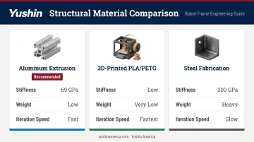
Aluminum extrusion (such as 80/20 T-slot profile) is the most practical starting point: stiff enough for light payloads, light enough to keep actuator force requirements manageable, and easy to reconfigure.
Every joint connection point must allow angular rotation. As the actuator extends and retracts, the arm geometry changes, and any mounting point that cannot pivot will bind. TiMOTION confirms that clevis plus mounting pin is the most common electric actuator mounting technique because it accommodates this rotation.
Skill and Safety Readiness
Required knowledge before starting:
- Basic electronics wiring and circuit protection
- A CAD model or dimensioned sketch of the full arm layout
- Microcontroller programming and PWM control fundamentals
Required safety mechanisms before any load testing:
- Software travel limits hardcoded in firmware
- Current monitoring on each driver channel
- Mechanical end-stops at joint extremes to prevent actuator over-extension
- Watchdog timer to halt motion on software fault
How to Build a Robot Arm with Linear Actuators
Step 1: Design the Arm Structure and Calculate Force Requirements
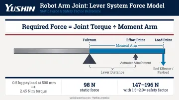
Model each joint as a lever system. The fulcrum is the joint pivot, the load point is the end effector plus payload, and the effort point is where the actuator attaches to the arm segment.
Required actuator force = Joint torque ÷ Actuator's perpendicular moment arm
Joint torque is load force multiplied by the moment arm length. Firgelli's actuator force guide recommends a 1.5–2.0× safety factor on top of the calculated static load.
Worked example — 500g payload at full extension:
A 0.5 kg payload at 500 mm from the joint creates a static torque of 2.45 N·m (0.5 kg × 9.81 m/s² × 0.5 m). With a 25 mm actuator moment arm, static actuator force is 98 N. Apply a 1.5–2.0× safety factor and the required actuator rating becomes 147–196 N — before accounting for arm segment mass or acceleration forces.
Keep these structural rules in mind during sizing:
- Base joints bear cumulative loads from every outboard segment — size them conservatively
- Stroke length must cover the full intended range of motion with margin
- At the extreme travel position, keep the actuator angle as close to perpendicular as possible to maximize effective force
Step 2: Assemble the Mechanical Frame and Mount the Actuators
Build in sequence from base outward: construct and level the base and swivel mount first, attach the first arm segment, then work progressively toward the end effector. Mount actuators between pivoting brackets before moving to the next segment.
Critical mounting rules:
- Both ends of every actuator must pivot freely — fix neither end rigidly
- All fasteners must be tight enough to eliminate play without restricting actuator rotation
- Misalignment of even a few degrees introduces eccentric loading, accelerated wear, and vibration that propagates through the entire structure
Cable routing must be planned during assembly, not retrofitted afterward. At every joint location:
- Use flex-rated wire and leave adequate slack at full range of motion
- Route cables through carriers or conduit to prevent abrasion
- Specify igus chainflex-class continuous-flex cable — standard hookup wire fatigues quickly at moving joints
Apply thread-locking compound to all fasteners at joint attachment points. Vibration from motor operation will loosen them over time.
Step 3: Wire the Control Electronics
The wiring architecture follows a clear hierarchy:
- Power supply feeds separate regulated rails — one for the driver stage (actuator voltage), one for the logic stage (microcontroller and sensors)
- Motor drivers connect to the driver power rail and receive PWM direction/speed signals from the microcontroller
- Actuators connect to motor driver outputs
- Feedback sensors (potentiometers to analog input pins, encoders to interrupt-capable pins) connect to the microcontroller
Match driver current rating to the actuator's stall current for the specific model in use. The Progressive Automations PA-14, for example, draws 5 A at full load; an undersized driver will thermally limit or fail under sustained operation. Keep power wiring short and heavy-gauge — long runs with undersized wire create resistive voltage drop that compounds any sag at the driver.
Step 4: Program the Microcontroller and Tune the Control Loop
The software runs as two coordinated layers:
- Low-level PID position loop — reads encoder or potentiometer feedback and adjusts PWM output. The University of Michigan's control systems reference uses a 1000 Hz (0.001 s) sampling period for digital DC motor position control, treating it as a real-time task. Aim for 100–1000 Hz depending on actuator speed.
- Upper motion layer — accepts target joint positions and translates them into individual PID setpoints
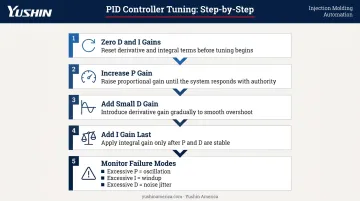
PID tuning sequence:
- Set derivative (D) and integral (I) gains to zero
- Increase proportional (P) gain until the arm responds to commands quickly
- Add small D gain to reduce overshoot and oscillation
- Add I gain last to eliminate steady-state position error under gravity loading
- Watch for common failure modes: excessive P causes oscillation, excessive I causes windup and instability, and excessive D amplifies sensor noise into jitter
Before any load testing, hardcode software travel limits, current monitoring, and a watchdog timer. All three are prerequisites for safe operation, not optional additions.
Key Parameters That Affect Robot Arm Performance
Four interdependent variables determine actual arm performance. Get one wrong and it degrades the rest.
Actuator Force Rating and Stroke Length
Force rating must exceed the calculated load under the worst-case configuration — arm fully extended horizontally, carrying rated payload, accelerating. Undersized actuators stall, overheat, or fail to hold position against gravity at extended reach. Stall conditions push current to maximum and sustain it, which is the fastest path to driver and actuator failure.
Stroke length constrains joint range of motion geometrically. Too short limits usable reach. Too long adds unnecessary mass to the moving arm and reduces structural stiffness — both of which degrade end-effector positioning.
Position Feedback Mechanism
Without real-time position feedback, the controller cannot detect or correct load-induced error. The arm drifts, and that drift compounds across multiple joints.
| Sensor Type | Accuracy | Limitation |
|---|---|---|
| Potentiometer | ±0.015–0.040 in. repeatability (10-bit ADC); ~0.1–0.3% stroke accuracy per Firgelli | Mechanical wiper wears over high cycle counts; not suited for sub-millimeter work |
| Optical encoder | Higher resolution; ±0.1 mm requires ≥10 counts/mm minimum | That's a resolution floor, not a guaranteed accuracy figure — control loop quality, structural compliance, and backlash each reduce it |
Motor and Drive Type
- DC gearbox motors — most common in off-the-shelf linear actuators, require H-bridge direction control and external encoder for position feedback
- Stepper motors — simpler, lower cost, 20–30% less expensive than comparable servo systems according to Kollmorgen, but torque drops significantly above 1000 RPM and they can lose position if load exceeds the pull-out torque curve
- Servo-driven actuators — maintain torque to 2000–4000 RPM with high-resolution feedback; the correct choice when repeatability under dynamic load is the priority
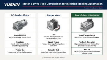
In demanding applications — injection molding take-out robots being one example — cycle time and repeatability tolerances leave no room for torque dropout or lost steps. Servo-driven systems are the only viable choice.
Structural Rigidity and Joint Alignment
Flex or play in the arm structure creates position error that no software loop can fully compensate. The controller reads encoder position, not actual end-effector position. If the arm deflects between those two points, the error is invisible to the control system — and it accumulates.
Misaligned joints compound the problem: binding under load accelerates actuator wear, and the resulting vibration propagates through the entire structure. Verify each joint moves freely through its full range, without stiffness or play, before connecting any actuator.
Common Mistakes and How to Troubleshoot Them
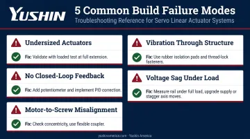
Most build failures trace back to five predictable errors.
Undersized actuators: Static load calculations often ignore acceleration forces and worst-case arm configurations. Validate with a loaded test at full horizontal extension before committing to the design.
No closed-loop feedback: Open-loop builds seem fine at first, then drift under sustained load or after extended cycles. Add a potentiometer at each joint and implement feedback-corrected control before calling the build complete.
Motor-to-screw misalignment: An off-axis connection between the motor shaft and lead screw causes eccentric rotation, vibration, and premature bearing failure. Check shaft concentricity and use a flexible coupler to handle minor offset.
Vibration through the structure: Small motor vibrations build into structural stress that cracks 3D-printed joints and loosens fasteners over time. Mount motors on rubber isolation pads and apply thread-locking compound to all fasteners at moving joints.
Voltage sag under simultaneous axis movement: Undersized power supplies cause motor controllers to misfire, drop steps, or trigger undervoltage shutdowns. Measure the supply rail under full simultaneous load — if it sags, either upgrade supply capacity or stagger axis moves to cut peak current demand.
When a Linear Actuator Robot Arm Is (and Isn't) the Right Choice
Where it works well:
- Prototyping and concept validation
- Research and laboratory automation
- Educational builds and coursework
- Light-duty pick-and-place with controlled payloads
- Applications where mechanical simplicity and direct force specification matter more than speed
Where it falls short:
For high-cycle production environments — injection molding take-out in particular — custom linear actuator builds cannot meet the reliability, speed, and service requirements that the application demands. Injection molding operations require robots that match machine cycle times precisely, operate lights-out over millions of cycles, and maintain consistent repeatability without manual intervention between maintenance intervals.
Purpose-built servo-driven systems like those in the Yushin America lineup are engineered from the ground up for these conditions. The FRA Series, for example, includes Active Vibration Control that counteracts arm oscillation during high-speed operation — a feature that enables shorter cycle times by eliminating the vibration settling delay after each traverse move.
The INTU LINE IoT system transmits production data and fault information to remote support teams in real time, enabling faster diagnosis and resolution without on-site technicians. These capabilities address specific failure modes in production molding environments — they don't emerge from iterating on a DIY build.
The decision framework:
- Exploratory, educational, or low-duty-cycle application → custom linear actuator arm is a cost-effective path
- Production reliability, high-cycle throughput, and lights-out operation → invest in an industrial robotic solution
Frequently Asked Questions
Which motor is best for a robotic arm?
It depends on the application. Servo motors deliver precise angular control with feedback and suit high-repeatability axes. Stepper motors hold position without encoders for simpler builds but lose torque at speed. DC gearbox motors with external encoders are common in linear actuator configurations, though servo-driven systems are generally preferred when repeatability under load is the priority.
What are the actuators used in robotic arms?
Three main types: electric linear actuators (lead screw and ball screw variants, most common in precision builds), rotary servo actuators (used at revolute joints), and hydraulic or pneumatic actuators (heavy-duty industrial arms). Electric linear actuators are preferred for most modern designs because of their precision, programmability, and clean operation.
What is the purpose of a linear actuator?
A linear actuator converts rotary motor motion into controlled straight-line displacement, allowing a robot arm joint to extend, retract, and hold position with measurable force — without the mechanical linkages that rotary servo conversions require.
Can I use servo motors instead of linear actuators for a robotic arm?
Yes. Servo motors work well for revolute (rotary) joints, and many successful arms use them exclusively. Linear actuators are better suited to prismatic joints, offer direct force specification, and avoid the mechanical backlash that linkage-based servo conversions introduce.
How precise can a robot arm with linear actuators be?
Arms using closed-loop feedback actuators routinely achieve repeatability in the ±0.1–0.5 mm range, adequate for most pick-and-place and positioning tasks. Absolute accuracy across multiple joints depends on structural rigidity, encoder resolution, and control loop quality, and degrades significantly without closed-loop feedback at each joint.