Introduction
Building a 5-axis robot arm sits squarely in the "moderately complex" category — not because any single piece is impossible, but because you're managing three disciplines at the same time. Mechanical assembly demands precise tolerances at every joint. Electronics require safe wiring of stepper drivers at 24V or higher. And programming must coordinate motion across five independent axes simultaneously.
Who can realistically take this on? Hobbyists or engineers with hands-on experience in 3D printing or fabrication, basic electronics knowledge, and some familiarity with microcontrollers like Arduino or ESP32. Complete beginners will face a steep learning curve. This is not a weekend project.
This guide covers each stage: choosing the right components, assembling the arm from base to wrist, wiring the electronics safely, and programming both manual control and position memory playback.
Key Takeaways
- Building a 5-axis robot arm demands mechanical, electronics, and programming skills — budget time and resources accordingly
- Core hardware includes stepper/servo motors, motor drivers, a microcontroller, bearings, GT2 timing belts, and structural parts
- Each axis controls one distinct movement: base rotation, shoulder extension, elbow elevation, wrist roll, and wrist pitch/yaw
- Belt slippage, motor overheating, and positional inaccuracy are the most common build failures — and all three are preventable
- Production-grade injection molding automation requires a different class of equipment entirely — DIY arms are best suited to learning and prototyping
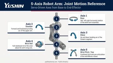
What Is a 5-Axis Robot Arm and How Do the Axes Work?
According to ISO 8373:2021, the correct term for independent motion in a robot is "axis" rather than degree of freedom. Each axis represents one independent movement — and five of them give a robot arm substantial spatial flexibility without the added complexity of a 6-axis design.
The Role of Each Axis
Here's what each axis actually does in plain terms:
| Axis | Joint | Movement |
|---|---|---|
| Axis 1 | Base | Left-to-right rotation of the entire arm |
| Axis 2 | Shoulder | Forward and backward extension along X and Y planes |
| Axis 3 | Elbow | Raises and lowers the upper arm for vertical reach |
| Axis 4 | Wrist Roll | Rotates the upper arm in a circular path to reorient the tool end |
| Axis 5 | Wrist Pitch/Yaw | Controls pitch and yaw movements of the end-effector |
As ASME notes, a 5-axis robot adds object rotation compared to a 4-axis unit, while a sixth axis adds full wrist roll/pitch/yaw orientation. NIST identifies the 6-axis configuration as the most common in industrial settings — but 5-axis arms cover a wide range of pick-and-place, palletizing, and assembly applications effectively.
In plastic injection molding, the axis count question becomes more specific. Production take-out robots — like those in the Yushin America lineup — are built around the kinematic demands of the molding cell itself: entry geometry, payload, and cycle time requirements all drive the axis configuration and motion profile, rather than general-purpose flexibility.
Parts and Tools Required to Build a 5-Axis Robot Arm
Getting the component list wrong costs you two rounds of shipping and a week of delay. Print a full BOM and cross-check it against your CAD files before ordering anything.
Structural Components
- 3D-printed structural parts — PLA or PETG at high infill density (60–80%) for load-bearing joints; aluminum alternatives for critical joints if repeatability matters
- Large main bearings — 20×47×14mm (ISO 6204 standard) for primary joints; NSK or SKF deep groove ball bearings are widely stocked and manufactured to tight ISO tolerances, which simplifies sourcing and keeps dimensional variation minimal
- Small secondary bearings — 4×10×4mm for rotation points
- GT2 timing belts — 2mm pitch profile; Gates and SDP-SI describe the GT2 curvilinear profile as engineered specifically for timing accuracy in precision applications like robotics
- Matching GT2 pulley wheels — sized to your gear ratios
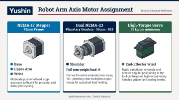
Motors and Gearboxes
Each axis carries a different load, so motor sizing is not one-size-fits-all:
- NEMA-17 steppers (42mm frame) — suitable for the base, upper arm, and wrist axes where loads are lighter
- Dual NEMA-23 steppers with planetary gearboxes (56mm frame, 10:1 ratio) — required for the shoulder joint, which carries the full arm weight
- High-torque servo (35kg·cm minimum) — for the end-effector wrist axis
When sizing gearboxes, account for efficiency losses — maxon's gear technology documentation puts this at roughly 10% per stage in a planetary gearbox. On a 10:1 two-stage unit, that's a meaningful torque reduction you can't ignore in your calculations.
Electronics
- Stepper motor drivers — TB6600HG or equivalent (Toshiba's datasheet rates it at 8–42V operating range, up to 4.5A continuous output)
- Microcontroller — ESP32 or Arduino; ESP32 is preferred if using dual-controller synchronization
- PCB — custom or commercial for signal and power distribution
- 24VDC power supply — size for peak combined draw; most 5-axis builds with NEMA-17/23 steppers run 15–20A at full load
- Wiring — do not undersize gauge; overloaded wire is a fire risk
Controller Input and Tools
For manual control, you'll need at minimum:
- Two joystick modules
- Toggle switches and push buttons
- A shared common ground across all inputs and the microcontroller — floating grounds cause erratic behavior
Tools required:
- 3D printer with 300×300mm or larger bed (split large parts if necessary)
- Soldering iron and solder
- M3/M4/M5 nuts and bolts
- Wire strippers, hex keys, screwdrivers
- Clamps or bearing press for fitting bearings — never hammer bearings in
How to Build a 5-Axis Robot Arm: Step-by-Step Assembly
Physical assembly runs base-up in a fixed sequence. Skipping steps — particularly bearing seating and belt tensioning — creates problems that are nearly impossible to correct once the arm is complete.
Step 1: Design and Print the Frame
Download or design your CAD files before printing a single part. Key printing rules:
- Use higher infill (60–80%) for shoulder and base components — these carry the most load
- Use standard infill (30–40%) for lighter upper arm and wrist sections
- If your print bed is smaller than the design requires, split large parts and join with bolts — include alignment features in the split geometry
Step 2: Assemble the Base
- Mount the NEMA-17 stepper into the base plate and attach a small pulley to the motor shaft
- Press-fit the large main bearing into the base using a clamp — do not hammer it in
- Seat the secondary bearings using M4 nuts and bolts
- Slide the rotational base component into the main bearing
- Route the GT2 timing belt around the base axis and motor pulley — keep the belt as short as possible while still fitting
- Install belt tensioners to prevent slippage under load
Step 3: Build the Arm Joints (J1 and J2)
- Attach custom pulley wheels to each NEMA-23 gearbox shaft using M5 bolts and press-fitted nuts
- Mount both NEMA-23 motors into the J1 base bracket
- Press-fit joint bearings on both sides and insert the J1 mount attachments through them
- Slide J1 over the mounts and bolt into place
- Route and tension timing belts for each joint — belts must be short enough to maintain tension but long enough to install
Step 4: Install the Upper Arm and Wrist
- Attach the NEMA-17 with its gearbox to the J1 body
- Mount J2 over the bearings
- Install the wrist assembly using a NEMA-17 with a higher-ratio gearbox (27:1 recommended)
- Attach the high-torque servo to the end-effector mount using M3 bolts
- Connect the servo horn and any 3D-printed adapter
- Press-fit the final bearing into the servo mount — this distributes gravitational load away from the servo shaft
With the mechanical assembly complete, turn your attention to the electrical side.
Step 5: Wire the Electronics
- Connect each stepper motor's coil wires (blue/red/green/black for A+/A-/B+/B-) to the corresponding driver
- Route DIR and PUL signals from the microcontroller to the PCB
- Connect the wrist servo and any accessory servo to their PCB headers
- Wire all controller inputs (joysticks, buttons, switches) with a shared common ground
- Double-check voltage levels before powering on — verify 24V is not reaching 5V logic pins
Programming and Configuring Your 5-Axis Robot Arm
Setting Up the Development Environment
Install the Arduino IDE, add the ESP32 board support package from Espressif's documentation, then install the AccelStepper library via Library Manager.
AccelStepper, authored by Mike McCauley, provides an object-oriented interface for stepper motor control with built-in support for acceleration, deceleration, and multiple simultaneous steppers running independently. Smooth acceleration is non-negotiable — hard starts cause positional errors and belt skip.
Writing Motor Control Code
Core programming structure:
- Declare each stepper in the AccelStepper class with its STEP and DIR pin assignments
- Set max speed values in steps per second per motor
- Map joystick analog values to motor movement commands — include deadzone filtering (typically ±10 counts) to prevent drift when joysticks are at rest
- Configure servo control using standard PWM mapping for the wrist axis
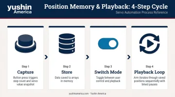
Implementing Position Memory and Playback
Position memory is what separates a functional arm from a genuinely programmable one:
- When a save button is pressed, capture current step counts for all steppers and potentiometer values for servos, storing them to arrays
- A mode switch toggles between user control and playback
- The playback loop iterates through saved positions in sequence
- Record timing delays between positions — the arm should pause naturally at each saved point rather than rushing between them
Once position memory is working on a single controller, multi-controller builds introduce a coordination problem that needs explicit handling.
Synchronizing Dual Microcontrollers
If you're running two ESP32s to manage different axis groups:
- Use digital handshake signals — one controller sends HIGH only when its motors have reached target positions
- The second controller waits for that signal before proceeding
- Without this handshake, axes drift out of phase during playback — a saved sequence that looked correct in testing will produce different positions every run
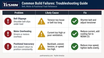
Common Build Problems and How to Fix Them
These three issues account for most first-build failures — and all of them are correctable.
Belt Slippage on the Shoulder Joint
Problem: The shoulder timing belt slips under load, reducing effective payload.
Likely cause: Belt tension too loose, tensioner bearings poorly positioned, or belt too long.
Fix:
- Reduce belt length incrementally — shorter is almost always better
- Adjust tensioner bearing positions to increase contact area
- SDP-SI's belt design guidance confirms that when torque exceeds the belt's holding capacity, tooth-jumping occurs — increase tension gradually until operation is stable
- If slippage persists at design payload, increase the number of belt teeth in contact by redesigning the pulley geometry
Motor Overheating
Problem: Stepper drivers or motor bodies become excessively hot, causing reduced performance or driver shutdown.
Likely cause: Current settings too high, insufficient ventilation, or poor-quality driver ICs.
Fix:
- Source drivers from verified suppliers with traceable datasheets
- Reduce driver current to the minimum that still achieves required torque — FAULHABER's thermal analysis identifies Joule losses as the primary heat source in steppers, directly proportional to current squared
- Add a small cooling fan to the NEMA-23 shoulder motors specifically — they run hottest due to sustained load
Positional Inaccuracy and Jumpiness
Problem: The arm doesn't return to the same position consistently, or movement appears jerky.
Likely cause: 3D-printed part tolerances creating joint backlash, uneven belt tension, or max speed set too high.
Fix:
- Reduce max speed settings in code — motors skip steps when pushed beyond their torque curve
- Tighten all belts evenly across axes
- Note that printed plastic tolerances are amplified at arm length — a 0.5mm slop at the joint becomes several millimeters at the tool end
The HELENE open-source 6-axis PLA arm studied in MDPI Robotics (2025) achieved 0.87mm repeatability error after deliberate optimization. A first-time DIY build will likely land worse — that's normal, and iteration is how you close the gap.
Pro Tips for a Successful Build
Before you start:
- Print and verify the full BOM against your CAD files
- Note which bearings are press-fit versus bolt-mounted
- Confirm your printer can handle the largest single-piece parts
- Label all wires during assembly — tracing unlabeled wires in a completed arm is genuinely painful
During assembly:
- Test each joint independently before adding the next one
- Power just that motor, verify smooth motion, check for reversed direction — catching a misaligned belt at the joint stage saves hours of disassembly
Understanding the ceiling of DIY:
A well-built 5-axis arm using 3D-printed parts can achieve repeatability around ±2mm, which is adequate for education, prototyping, and light-duty tasks. The Forte, a 2025 fully 3D-printable 6-DoF manipulator documented on arXiv, achieved 0.467mm repeatability — but required careful engineering choices that go beyond a typical hobby build.
For production environments (injection molding part extraction, IML cells, palletizing), that ±2mm figure becomes a liability. Yushin America's production take-out robots like the RC-SE and TSXA are engineered with premium servos, vibration-tuned beams, and finer motion-control resolution specifically for IML label registration and medical/pharma part handling, where placement tolerances are far tighter than any 3D-printed arm can sustain.
The RC-SE operates on presses from 100–800 tons with a 4–12kg payload, built to run continuously in lights-out production cells. That level of precision and uptime reliability simply isn't achievable at the DIY tier — and knowing that boundary helps you scope your build honestly from the start.
Frequently Asked Questions
How many axes does a robot arm have?
Most industrial robots have between three and seven axes, with four-, five-, and six-axis configurations being most common. Industry standards generally require at least three axes for a machine to qualify as an industrial robot. More axes generally means greater spatial flexibility and the ability to handle more complex tasks.
What is a 6-axis robot arm?
A 6-axis arm adds a sixth rotational joint — typically a full wrist rotation — to the five-axis configuration. This gives the end-effector an additional degree of freedom, allowing it to approach a target point from virtually any angle. The 6-axis configuration is the most common articulated robot found in industrial settings today.
What is the difference between a 5-axis and 6-axis robot arm?
The key difference is the extra wrist rotation on a 6-axis arm, which provides full orientation control in 3D space. Five-axis arms handle palletizing, pick-and-place, and most assembly tasks effectively. Six-axis arms are preferred for welding, painting, and any task requiring tool approach from an arbitrary direction.
What motors are best for a DIY 5-axis robot arm?
A combination works best: NEMA-17 steppers for lighter axes (base, upper arm, wrist) and NEMA-23 steppers with planetary gearboxes for the shoulder joint, which carries the most load. A high-torque servo motor (35kg·cm or more) handles the wrist end-effector axis.
How accurate can a homemade 5-axis robot arm be?
Well-built DIY arms using 3D-printed parts typically achieve repeatability around ±2mm. Accuracy improves with tighter belt tension, higher-infill printed parts, and reduced motor speed — but plastic tolerances and belt backlash set a practical ceiling no matter the build quality.
Can a DIY 5-axis robot arm be used in industrial applications?
Generally not. DIY arms lack the payload capacity, repeatability, speed, and continuous-duty ratings that production environments require. Tasks like injection molding part extraction demand purpose-engineered robotic systems that deliver sustained uptime and high positional precision across thousands of cycles per shift — something only purpose-built take-out robots are rated to provide.