Introduction
Walk through any plastics manufacturing facility and injection molding machines (IMMs) are everywhere. They produce automotive clips, medical syringes, food container lids, and electronics housings — often running 24 hours a day. The global injection molded plastics market sits at USD 362.47 billion in 2025, projected to reach USD 481.42 billion by 2033, with packaging alone accounting for 30.35% of revenue.
Yet most plant-floor personnel understand the output but lack a clear mental model of what the machine actually does to produce it. That gap creates real problems: poor machine selection, inefficient cycle times, and quality issues that are difficult to diagnose.
This guide breaks down how an injection molding machine works, what its core components do, and why each stage of the production cycle matters.
Key Takeaways
- An IMM melts plastic pellets, injects the melt into a closed mold under pressure, holds it while it cools, then ejects the finished part
- Four subsystems drive every machine: injection unit, clamping unit, drive unit, and control system
- Every cycle follows the same sequence: clamping → plasticization and injection → cooling → ejection
- Clamping force (tons) and injection volume (grams) are the two most critical specification parameters
- All-electric machines are the fastest-growing drive type — they typically draw 30–50% less energy than hydraulic equivalents
What Is an Injection Molding Machine?
An injection molding machine (IMM) produces plastic parts by injecting molten thermoplastic material into a precision mold cavity, where it cools and solidifies into the finished shape. The screw rotates to melt raw pellets, then shifts to ram mode — forcing the melt into a closed, cooled mold until the part solidifies and ejects.
No alternative process matches that combination of speed, repeatability, and geometric complexity at production scale. Blow molding shapes hollow parts like bottles; extrusion produces continuous profiles. Injection molding is a fill-and-cool process — the mold closes, fills, packs, and opens for each discrete part.
What Materials IMMs Process
Most industrial IMMs process thermoplastics. Specialized machines or equipment packages handle:
- Thermosets — cure irreversibly under heat; require screw purge controls and shorter residence times
- Liquid silicone rubber (LSR) and solid silicone (HTV/HCR) — need cooled barrels and heated molds, the reverse of thermoplastic setup
- Bioplastics and recyclates — used in sustainable packaging and compostable consumer goods, with tighter processing windows than virgin resins
Material choice directly affects machine settings, screw design, and cycle parameters — which is why specifying the right machine starts with knowing the material.
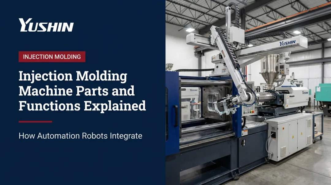
Main Components of an Injection Molding Machine
An IMM consists of four integrated subsystems: the injection unit, the clamping unit, the drive unit, and the control system. Each plays a distinct role; none operates independently.
Injection Unit
The injection unit receives raw plastic pellets, melts them into a consistent melt, and delivers that melt into the mold under controlled pressure. Its core elements:
- Hopper — holds raw pellets and feeds them into the barrel
- Barrel — heated cylinder housing the reciprocating screw
- Reciprocating screw — performs two distinct functions (see below)
- Nozzle — transfers melt from the barrel into the mold
The screw serves two distinct functions. During plasticization, it rotates to convey and melt pellets through three zones — feed, compression, and metering — building a homogeneous melt at the screw tip. During injection, it stops rotating and moves forward axially, pushing the melt like a plunger.
A non-return (check) valve at the screw tip prevents backflow during injection, acting as a one-way seal. Plastics Technology notes injection pressures in the range of 20,000–45,000 psi at this stage.
Clamping Unit
The clamping unit holds the two mold halves together during injection and cooling, then opens them for ejection. Key elements:
- Fixed and moving platens — the structural faces that hold each mold half
- Tie bars — guide platen movement and define the spacing available for mold installation
- Clamping mechanism — generates and holds closing force
Two primary clamping mechanisms exist:
| Type | How It Works | Typical Range |
|---|---|---|
| Toggle (mechanical) | Crankshaft linkage multiplies force — efficient and high-output | 500–4,000 kN (KraussMaffei data) |
| Direct hydraulic | Cylinder applies force directly — compact but lower tonnage ceiling | 500–55,000 kN depending on model family |
Clamping force must be sufficient to resist the mold-opening force created by cavity pressure over the part's projected area. When it isn't, the mold gaps and plastic escapes as flash — a defect directly traceable to insufficient clamp specification.
Drive Unit and Control System
The drive unit powers screw rotation, axial screw movement, and mold opening and closing. Modern machines use electric servo motors, hydraulic systems, or a hybrid of both — each with different tradeoffs in energy efficiency, speed, and force output.
The control system ties everything together. Sensors throughout the machine feed real-time data back to the controller, which regulates:
- Pressure — injection and holding pressure at each stage
- Temperature — barrel zones, nozzle, and mold
- Injection speed — fill rate and velocity profiles
- Cycle timing — coordination of every machine event
This closed-loop feedback keeps part dimensions, surface quality, and cycle consistency stable across thousands of shots.
How Does an Injection Molding Machine Work?
The IMM operates through a repeating, timed cycle. Each stage depends on the previous one completing correctly — deviations ripple through part quality, cycle time, and mold condition.
Mold Clamping
The cycle begins when the two mold halves close and lock. The motion isn't simply "fast close." It follows a programmed three-phase profile:
- High-speed close — the moving platen travels quickly toward the fixed platen
- Slow mold protect — the machine slows as the halves approach contact, protecting the mold face if any obstruction is present
- High-pressure lock — full clamping force is applied and held throughout injection
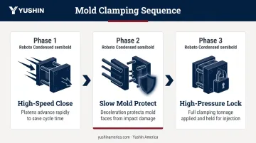
This sequence protects expensive tooling from damage while still minimizing the time the mold spends opening and closing.
Plasticization and Injection
While the previous cycle's part was cooling, the screw was already rotating to prepare the next shot. During plasticization:
- Pellets feed from the hopper into the barrel's feed zone
- The screw's rotation and barrel heater bands melt and mix the material through the compression and metering zones
- A homogeneous melt accumulates at the screw tip, pushing the screw backward as volume builds
Once the correct shot volume accumulates, the screw stops rotating and drives forward — injecting the melt through the nozzle into the mold cavity. Fill speed and injection pressure directly affect surface finish, weld lines, and dimensional accuracy.
Packing/holding pressure follows immediately after cavity fill. The machine maintains reduced pressure momentarily to compensate for material shrinkage as it cools. Too little hold pressure causes sink marks or voids; too much creates residual stress or part sticking.
Cooling and Solidification
Cooling begins the instant melt contacts the mold walls. It's also the longest phase of the cycle — Plastics Engineering cites cooling as typically 50–70% of total cycle time, and Plastics Technology notes it can be 80% or more for thicker-walled parts.
Key variables that control cooling time:
- Wall thickness — the dominant factor; thicker walls need more time
- Mold temperature — controlled via water channels running through the mold
- Material thermal properties — conductivity and specific heat vary by polymer
- Cooling channel placement — channels positioned close to the cavity reduce cooling time
While the part cools, the screw is already rotating to pre-plasticize the next shot — meaning plasticization and cooling run in parallel, recovering time that would otherwise be wasted.
Ejection
Once the part reaches sufficient rigidity, the clamping unit opens the mold and ejector pins — actuated by an ejector cylinder — push the part free from the cavity. The cycle then restarts immediately.
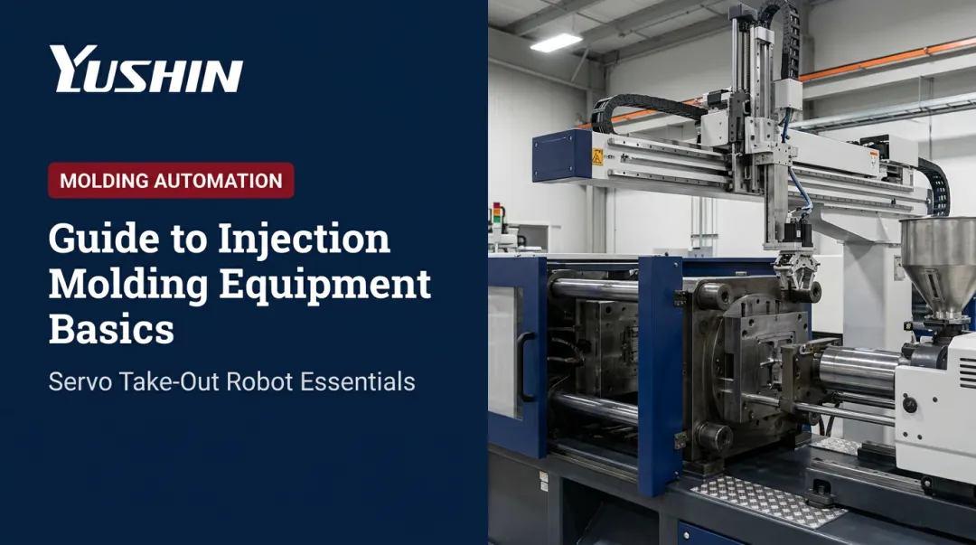
Ejection is more consequential than it looks. Manual part retrieval introduces inconsistency: operators vary in speed, position, and attention — affecting both cycle time and mold surface condition. That's why take-out robots are standard in high-volume cells.
Yushin America's take-out robots — including the YD/YD2 series for general-purpose presses (30–500 tf) and the HST and HSA series for fast-cycle packaging cells — integrate directly with IMM controls. The HST-150S, for example, achieved a 0.5-second take-out time on an 8-cavity thin-wall part within a 3-second overall molding cycle. Consistent, repeatable part removal at that speed isn't achievable manually.
Types of Injection Molding Machines
IMMs are classified primarily by their drive system. The choice affects precision, energy consumption, noise, and upfront cost.
| Drive Type | Characteristics | Best Suited For |
|---|---|---|
| Hydraulic | Durable, high-force capability, widely deployed globally | Large parts, thick walls, high-tonnage applications |
| Toggle (mechanical) | Crankshaft linkage multiplies clamping force efficiently | High-cycle, mid-tonnage production |
| All-electric | Servo-driven, higher repeatability, quieter, lower energy use | Precision parts, cleanroom, medical, fast cycles |
| Hybrid (servo-hydraulic) | Combines electric precision with hydraulic force | Applications needing both speed and high tonnage |
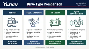
All-electric machines are the fastest-growing segment. Sumitomo Demag reports over 88,000 all-electric installations globally, with up to 80% energy savings versus hydraulic equivalents. MarketsandMarkets identifies all-electric as the leading growth category. For high-precision and cleanroom applications — medical devices, optics, micromolding — all-electric has become the dominant choice.
Drive system aside, machine orientation matters too. Most IMMs are horizontal, but vertical machines serve insert molding applications where gravity assists insert loading before overmolding. Yushin's V-HOP, V-HOP-II, and SVR-C50 robots are designed for vertical-press cells, handling sprue extraction and part removal on rotary-table and shuttle-press configurations.
Where Injection Molding Machines Are Used
IMMs appear wherever plastic parts require high volume, tight tolerances, and repeatable geometry. Machine specifications — clamping force, shot size, material compatibility — differ significantly across sectors.
Each major end market drives distinct machine requirements:
- Automotive — Large-tonnage presses (1,000+ ton) produce bumper fascias, instrument panel substrates, door panels, and connectors. Long cycle times, large shot sizes, and heavy downstream handling are standard. Take-out robots at this scale handle payloads of 30–80+ kg.
- Medical — All-electric machines dominate, often in cleanroom configurations. Applications range from syringes and IV components to surgical instruments and diagnostic disposables. Robots operating here require ISO Class 6 certification, FDA-grade lubricants, and sealed bearings.
- Packaging — The largest end-market segment at 30.35% of injection molded plastics revenue. Thin-wall containers, caps, closures, and dairy packaging run at extreme speeds. Netstal has documented a 4-cavity PP thin-wall dairy cup at a 2.7-second cycle — throughput where take-out time becomes a meaningful fraction of overall cycle time.
- Consumer goods and electronics — Power tool handles, appliance housings, connectors, and appliance components. Machine specs vary widely based on part size and resin, with no single dominant configuration.
Frequently Asked Questions
What does an injection molding machine do?
An IMM melts plastic pellets and injects the molten material into a closed mold cavity under pressure, where it cools and solidifies into a finished part. The same cycle repeats continuously — clamping, injection, cooling, ejection — enabling high-volume production of consistent parts.
How much does an injection molding machine cost?
Cost varies by clamping force, drive type, platen size, and manufacturer. All-electric machines have historically run about 20% more than comparable hydraulic units, though Plastics News reported in 2024 that gap has narrowed considerably over 15 years.
What are the main types of injection molding machines?
The four types — hydraulic, toggle (mechanical), all-electric, and hybrid (servo-hydraulic) — differ primarily by drive system. All-electric machines are the fastest-growing segment, driven by their precision, repeatability, and energy efficiency advantages in medical and high-speed packaging applications.
What is clamping force and why does it matter?
Clamping force (measured in tons or kilonewtons) is the force applied to keep mold halves closed during injection. It must exceed the mold-opening force generated by cavity pressure acting on the part's projected area. Insufficient clamping force allows the mold to gap under injection pressure, producing flash and defective parts.
How long does an injection molding cycle take?
Cycle time varies widely by part size, wall thickness, and material. Thin-wall packaging can run at 2.7 seconds (Netstal, 4-cavity PP dairy cup). Larger automotive parts can take 60 seconds or more. Cooling is consistently the longest phase — typically 50–70% of total cycle time, and 80% or more for thick-walled parts.