When a short shot appears, or flash shows up on every cycle, or cooling time creeps upward without explanation, the cause almost always traces back to a specific machine component underperforming. This article breaks down each major part, explains its function, walks through how all the parts work together during the molding cycle, and covers what goes wrong when any one component fails to hold its specification.
Key Takeaways
- An injection molding machine has three primary units: the injection unit (melts and injects material), the clamping unit (holds the mold), and the power/control unit (drives all movements)
- The mold is a fourth critical element — housing the cavity, core, runner system, and cooling channels that determine part shape and quality
- Components are interdependent — a worn screw or misaligned tie bar cascades directly into part defects and unplanned downtime
- Cooling accounts for 50–80% of total cycle time, making the cooling system the primary target for efficiency improvements
- Take-out robots integrate with the ejector and control unit to cut cycle time and eliminate manual handling risk
What Is an Injection Molding Machine?
An injection molding machine is a precision manufacturing system that melts thermoplastic or thermoset material and forces it under pressure into a closed mold, where it solidifies into the exact shape of the cavity. The British Plastics Federation describes injection molding as one of the prime processes for producing plastic articles — well-suited for high-volume manufacture because tooling costs are offset by per-part economics at scale.
That scale is significant: the global injection molded plastics market was valued at USD 362.5 billion in 2025, spanning automotive, medical, packaging, and consumer goods production.
Two points of terminology cause consistent confusion:
- Machine vs. mold: The "machine" refers to the full equipment unit — injection unit, clamping unit, and power system. The "mold" or "tool" is a separate, interchangeable component mounted onto the machine. They are distinct physical assets.
- Tonnage vs. weight: Machine tonnage refers to the clamping force that holds the mold closed against injection pressure — not the machine's physical weight. It is a primary specification when selecting equipment.
Unlike extrusion or blow molding, injection molding uses a closed, pressurized cavity to produce discrete, near-net-shape parts with tight dimensional tolerances in short cycle times. Understanding each component of the machine — and what it does — is the foundation for optimizing that process.
Main Parts of an Injection Molding Machine and Their Functions
Injection Unit
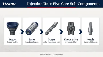
The injection unit handles material preparation and delivery. It takes solid plastic pellets from the hopper, melts them in the heated barrel, and injects the molten material into the mold at controlled speed and pressure.
Sub-components and their roles:
- Hopper — stores and gravity-feeds dry pellets into the barrel inlet
- Barrel — a heated steel cylinder housing the reciprocating screw; heater bands maintain zone-by-zone temperatures along its length
- Screw — rotates to melt, mix, and homogenize plastic while building up a measured "shot" of material at its tip; general-purpose screws typically run an L/D ratio of 18:1 to 25:1 and a compression ratio of 2.0–3.0
- Check valve — a non-return valve at the screw tip that prevents molten material from flowing back up the barrel during injection
- Nozzle — directs molten plastic into the mold's sprue bushing, sealing against the mold face to prevent leakage
One critical distinction: injection speed and injection pressure are controlled independently. Speed governs how quickly the melt front fills the cavity; pressure compensates for shrinkage during pack. Treating them as a single variable is one of the most common process troubleshooting mistakes.
That process control only holds if the screw-to-barrel clearance stays within spec. New clearance runs approximately 0.004–0.006 in. for a 50 mm screw and 0.007–0.010 in. for a 90 mm screw, per Xaloy/SPI guidance. Plastics Technology notes that replacement is commonly considered when flight clearance reaches 4× the original tolerance — at that point, leakage flow increases melt temperature and shot-weight consistency degrades noticeably.
Clamping Unit
The clamping unit does two things: holds the mold firmly shut against injection pressure during filling, and opens the mold after cooling to allow part ejection. Clamping force — measured in tons — is one of the most critical machine specifications.
Key sub-components:
- Stationary platen — fixed to the machine frame; mounts one mold half
- Movable platen — slides along tie bars to open and close the mold
- Tie bars — precision steel rods that guide platen movement and distribute clamping force evenly; the distance between tie bars defines the maximum mold size the machine can accept
The clamping mechanism is either toggle (a mechanical linkage that magnifies hydraulic cylinder force to lock the mold) or direct hydraulic. Each has trade-offs in force profile, energy use, and speed of response.
Once the mold opens, part removal falls to the ejector system — also housed within the clamping unit. A hydraulic cylinder drives ejector pins or plates through the B-side of the mold to push the finished part free. Improper ejection force or poor pin placement causes part deformation, surface marks, or sticking — problems that get misattributed to process parameters when the real cause is mechanical.
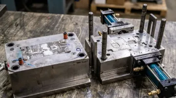
Mold
The mold is the interchangeable tooling component that defines part geometry. It consists of two halves — the A-side cavity and the B-side core — that, when closed, form the hollow space the plastic fills.
The mold mounts to the machine's platens but is not part of the machine itself. Its design dictates nearly every quality outcome.
The mold's internal systems:
| System | Function |
|---|---|
| Runner system (sprue, runners, gates) | Channels molten plastic from nozzle into the cavity |
| Cooling channels | Circulate water or coolant to extract heat and control solidification rate |
| Venting system | Releases trapped air to prevent burn marks, voids, or incomplete fill |
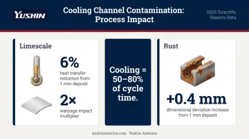
Cooling dominates the cycle time equation. RJG research reports that cooling can represent up to 80% of the molding cycle, while Plastics Engineering and Ronningen Research cite a range of 50–80% depending on part geometry and mold design. Either way, it is the dominant cycle-time lever.
Cooling channel condition matters as much as cooling channel design. A 2025 Scientific Reports study found that just 1 mm of limescale in cooling circuits reduces heat transfer efficiency by 6%, and 1 mm of rust increases warpage by 0.4 mm — with limescale doubling that warpage impact.
Control and Power Unit
The control unit is the machine's operating brain. Operators set and monitor all cycle parameters — injection speed, pack pressure, barrel temperatures, clamping force, cooling time, ejection stroke — through a human-machine interface (HMI). Modern controllers store recipes for each mold and detect out-of-tolerance conditions in real time.
Power system options:
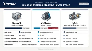
- Hydraulic machines — use a pump, valves, and cylinders to generate movement; known for high force capacity and suitability for large tonnage applications
- Electric machines — use servo motors for each axis, delivering greater precision, repeatability, and energy efficiency
- Hybrid machines — combine both, typically using servo-electric for injection and hydraulic for clamping
The numbers make the case directly. An ACEEE case study found hydraulic machine energy consumption at 0.278 kWh/lb versus 0.073 kWh/lb for an all-electric machine. An ILSAG/ExxonMobil industry study reports high-performance all-electric machines can be up to 80% more energy efficient than 20-year-old hydraulic predecessors.
How All the Parts Work Together: The Injection Molding Cycle
The molding cycle is a repeating sequence of timed events executed in coordination by all machine units. Cycle time is the primary productivity metric operators track — every second saved across thousands of shots compounds into significant output.
Step 1: Mold Close and Clamp
The cycle begins when the clamping unit drives the movable platen forward, closing the two mold halves precisely along the parting line. The toggle or hydraulic mechanism then applies full clamping force. Insufficient clamp tonnage at this stage causes flash — molten material escapes through the parting line because injection pressure exceeds the closing force.
Clamping force is calculated as cavity pressure × total projected area. Keyence gives typical cavity pressure at 300–500 kgf/cm², and the formula accounts for runners and gates in the projected area calculation, not just the part itself.
Step 2: Injection and Pack
With the mold locked, the injection unit drives the screw forward like a plunger. Molten plastic moves through the nozzle, into the sprue, through the runner system, and into the mold cavity at high speed.
Once the cavity is approximately 98% full, the machine switches from velocity control to pack pressure. This transition — the velocity/pressure (V/P) switchover — is critical. Pack pressure compensates for volumetric shrinkage as the material cools and gates freeze off. Fill speed and pack pressure are separate control stages and require separate troubleshooting logic.
Step 3: Cooling and Screw Recovery
Cooling begins the moment molten plastic contacts the mold walls. Two things happen simultaneously:
- The part solidifies while held under pack pressure until the gate freezes — after gate freeze-off, no additional material can enter the cavity
- The screw rotates backward, plasticizing and metering the next shot
Overlapping screw recovery with cooling is how machines minimize non-productive time. Gate freeze-off marks the point when pack pressure no longer has any effect; holding pressure beyond that point wastes time without quality benefit.
Step 4: Mold Open and Part Ejection
Once the part has cooled sufficiently to hold its dimensions, the clamping unit retracts the movable platen. The ejector system advances, driving ejector pins through the B-side of the mold to push the part free.
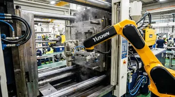
This is where take-out robots integrate directly with the machine's cycle. Yushin's servo-driven systems — from the YD/YD2 Series (covering 30–500 ton presses) to the MKA-2000S (1,500+ ton presses) — synchronize with the machine's ejector signal to enter the mold space, extract the part, and clear before the next clamp close.
Motion control matters at this stage. Yushin's HX/SoftStop motion algorithms decelerate the robot arm smoothly at part contact, reducing shock on freshly molded parts that are still thermally soft. The FRA Series adds Active Vibration Control for high-value cosmetic parts where arm oscillation during high-speed traversal would otherwise risk damage or misplacement.
Compared to manual removal, robot extraction delivers measurable advantages:
- Eliminates cycle-to-cycle inconsistency caused by human reaction time variation
- Prevents part damage from uncontrolled ejection drops
- Removes operators from the hazard zone adjacent to the press
Key Factors That Affect Machine Performance
Material Properties
Melt flow index, viscosity, and moisture content directly determine barrel temperatures, screw speed, and injection pressure settings. Running a material outside its specified processing window degrades part quality and can damage the screw and barrel.
Moisture is critical to control. Covestro specifies residual moisture targets of 0.01–0.02% for polycarbonate grades before molding — excess moisture causes hydrolytic degradation that reduces molecular weight and produces brittle parts, even when the surface appears acceptable. Defect signatures include silver streaks, splay, delamination, and voids.
Mold Condition
Machine parameters can't compensate for mold-side problems:
- Worn parting surfaces cause flash regardless of clamping force
- Partially blocked cooling channels increase cycle time and cause warpage
- Gate erosion affects fill balance and leaves excessive vestige height
Teams frequently misattribute these tooling issues to machine parameters, chasing process adjustments that can't solve a mechanical root cause.
Machine Wear
Screw and barrel wear, which reflects the gradual increase in clearance between screw flights and the barrel wall, reduces shot consistency and injection pressure accuracy over time. Two failure modes are worth tracking in parallel:
- Screw/barrel clearance: Monitor through shot-weight variation tracking — increasing variation on stable materials and parameters is the clearest early signal. Periodic dimensional checks confirm whether replacement is approaching.
- Hydraulic seal degradation: Produces inconsistent injection pressure response, slow clamp movement, and pressure that won't hold during pack.
Common Misconceptions About Injection Molding Machine Parts
A few persistent assumptions lead to misdiagnosed defects and accelerated machine wear. Here are three worth correcting directly.
"Higher clamping tonnage produces better parts." Clamping force only needs to exceed the force generated by injection pressure acting on the projected area. Running excess tonnage accelerates wear on platens, tie bars, and the mold without any quality benefit. Plastics Technology notes that excess clamp tonnage actually narrows the process window and can cause poor venting, leading to short shots, burn marks, and weld lines.
"Short shots mean I need more injection speed." Fill speed and pack pressure serve different functions. A short shot caused by insufficient pack pressure or a frozen gate won't respond to increased fill speed — it may actually worsen surface quality. Identify which phase of the cycle is underperforming before adjusting parameters.
"The mold and machine are one system." A mold validated on one machine may perform differently on another if barrel temperature calibration, injection response, or tie bar alignment differs. Machine-specific process documentation matters. Molds are tooling assets that move between machines; treat them as separate from the press they're currently running on.
Frequently Asked Questions
What are the main parts of an injection molding machine?
An injection molding machine has three primary units: the injection unit (melts and delivers material), the clamping unit (holds the mold closed and ejects parts), and the power/control unit (drives all movements and governs cycle parameters). The mold is a separate, interchangeable tool mounted to the machine's platens.
What are injection molded parts?
Injection molded parts are discrete plastic components produced by injecting molten material into a closed mold under pressure. The process serves industries from automotive and medical to packaging and consumer goods, producing parts ranging from micro-scale connectors to large bumper fascias.
What is the difference between a hydraulic and an electric injection molding machine?
Hydraulic machines use pumps and cylinders for motion, providing high force capacity but lower energy efficiency. Electric machines use servo motors for each axis, delivering greater precision, repeatability, and up to 80% less energy consumption than older hydraulic models. Hybrid machines combine both approaches.
What does clamping force mean in injection molding?
Clamping force is the tonnage applied to keep the mold closed against the pressure of injected material. It's calculated based on the projected area of the part and runners multiplied by cavity pressure — not selected arbitrarily. Running more tonnage than the calculation requires doesn't improve part quality.
How does the injection screw affect part quality?
The screw controls melt homogeneity and shot-to-shot consistency. Worn screw flights allow leakage flow back up the barrel, increasing melt temperature variability and producing inconsistent shot weights — which shows up as dimensional variation and surface defects in finished parts.
What is the purpose of the runner system in a mold?
The runner system — sprue bushing, runners, and gates — channels molten plastic from the machine nozzle into the mold cavity. Cold runner systems allow the runner to solidify with each shot, creating scrap for regrind; hot runner systems use a heated manifold to keep material molten, eliminating that solidified runner waste entirely.