This guide is written for engineers, product designers, NPI managers, and operations teams at injection molding facilities who need production-intent plastic parts in quantities between 100 and 10,000 units. It covers how the process works, which tooling and design decisions drive outcomes, and — critically — when small scale injection molding is the wrong answer entirely.
Key Takeaways
- Small scale injection molding uses aluminum or soft steel molds to produce 100–10,000 plastic parts at lower tooling cost than hardened production tooling
- It delivers production-equivalent material properties and dimensional accuracy that 3D printing cannot replicate
- Wall thickness, draft angle, and gate placement are the design variables that matter most — errors here compound tooling costs fast
- Below 100 parts, 3D printing or urethane casting almost always wins on total cost
- Automation applies at low volumes and directly impacts part consistency and mold longevity
What Is Small Scale Injection Molding?
Small scale injection molding is a manufacturing process where molten thermoplastic is injected under pressure into a mold cavity to produce plastic parts in limited quantities. Tooling is designed for lower shot counts — typically a few hundred to 10,000 cycles — rather than the millions of cycles demanded by hardened production molds.
That process definition points to the core goal: production-intent output. That means repeatable geometry, material properties consistent with the final product, and dimensional accuracy sufficient for real-world testing and assembly validation.
How It Differs from Other Methods
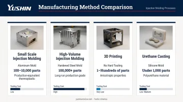
| Method | Tooling | Volumes | Material Properties |
|---|---|---|---|
| Small scale injection molding | Aluminum or soft steel mold | 100–10,000 parts | Production-equivalent thermoplastic |
| High-volume injection molding | Hardened P20 or H13 steel, multi-cavity | 100,000+ parts | Same, larger runs |
| 3D printing | No tooling | 1–hundreds | Anisotropic, not representative of molded parts |
| Urethane casting | Silicone molds | Under 1,000 | Polyurethane, not thermoplastic |
The 3D printing row in that table deserves a closer look. Printed prototypes don't capture the mechanical behavior, surface finish, or dimensional stability of injection-molded thermoplastics. That gap routinely causes design surprises that only surface after a full production mold has been cut — a costly correction at that stage of the process.
How the Small Scale Injection Molding Process Works
The physics are identical to high-volume molding. What changes is machine size, mold material, and the economics of setup relative to run length.
Raw thermoplastic pellets load into the machine hopper, melt under heat and screw rotation, and are injected under pressure into the mold cavity. The part cools, ejects, and the cycle repeats. According to RJG, cooling consumes roughly 80% of total cycle time — a figure that holds whether you're running 500 parts or 5 million.
Step 1: Mold Filling
Molten plastic travels through the runner system and enters the mold cavity through gates. Two runner system types apply here:
- Cold runners — lower tooling cost, some material waste from solidified runners, but well-suited to short production runs and low cavitation. Plastics Technology confirms cold runners have low initial capital requirements and are commonly chosen for exactly this scenario.
- Hot runners — engineered manifold systems that keep resin molten, reducing waste and improving consistency. Higher upfront cost makes them harder to justify unless run length and resin cost support the investment.
For most low-volume programs, cold runners are the practical choice. Plastics Technology also notes that parts should be 90–99% full after first-stage fill by volume — a control target that applies regardless of production scale.
Step 2: Cooling and Part Ejection
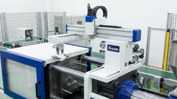
The part solidifies as heat dissipates through the mold. Ejector pins, hand loads, sliders, or lifters release the part once it has cooled sufficiently. At this stage, even low-volume cells benefit from automated part removal.
Compact take-out robots sized for smaller presses handle this efficiently. Yushin America's YD-0310 Servo Picker, compatible with presses in the 30–150 ton range, maintains part consistency, reduces cycle time, and minimizes handling damage during ejection.
Its servo-driven axes allow programmable extraction speeds — important when working with softer aluminum tooling, where abrupt ejection forces accelerate mold wear.
Step 3: Post-Processing
Common post-processing steps for low-volume runs include:
- Flash removal at the parting line
- Degating (separating parts from the cold runner)
- Surface finishing as required
- Secondary operations: insert assembly, pad printing, or ultrasonic welding
Flash frequency is directly tied to clamping pressure calibration and mold fit quality. With low-volume tooling, where cost per shot is higher, consistent ejection and minimal post-processing matter more, not less.
Tooling and Design Considerations for Low-Volume Molds
Tooling decisions made before the first chip is cut determine part quality, mold longevity, and whether the economics of a low-volume run make sense at all.
Mold Material Selection
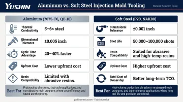
The choice between aluminum and soft steel is the first decision to make:
Aluminum alloys (7075-T6, QC-10):
- Faster heat transfer — Plastics Technology reports aluminum tools have thermal conductivity at least 5–6 times typical steel, enabling 20–40% faster cycle times
- Tolerances typically around ±0.005 inches per Fictiv's guidelines
- More prone to wear with abrasive or glass-filled resins
- Lower upfront cost for simple geometries
Soft/semi-hardened steels (P20, NAK80):
- Tighter tolerances (as tight as ±0.001 inches)
- Better suited for abrasive resins and high-temperature materials like polycarbonate
- Fictiv estimates P20 supports 50,000–100,000 shots before significant wear
- Higher initial cost, but better total cost of ownership with demanding materials
Steel molds aren't automatically too expensive for low-volume work. When your resin is glass-filled nylon or PEEK, aluminum erodes fast enough that a steel tool pays for itself well before the run ends. Material choice drives mold material selection — shot count is secondary.
Wall Thickness
Uniform wall thickness is the single most critical DFM constraint. Recommended ranges by resin:
| Resin | Wall Thickness Range |
|---|---|
| ABS | 1.14–3.56 mm |
| Polypropylene | 0.64–3.81 mm |
| Polycarbonate | 1.02–3.81 mm |
| Nylon | 0.76–2.92 mm |
Thick sections cause sink marks and voids. Thin sections risk short shots and trapped air. Both are worse in low-volume runs because tooling costs can't be amortized across high shot counts — every bad part hurts more.
Draft Angles
Insufficient draft causes part adhesion, mold scoring, and surface damage — particularly destructive with aluminum tooling. Follow these minimums:
- 0.5° minimum on all vertical faces
- 1° per inch of cavity depth as a rule of thumb
- 3° minimum for shutoffs
- 3–5° for textured surfaces depending on texture depth
Replace sharp internal corners with radii wherever possible. This reduces CNC machining complexity and eliminates stress concentrations in the molded part.
Gate Placement
Gate location controls fill pattern, weld line placement, and cosmetic outcome. Poorly placed gates push weld lines into structural or visible areas — a problem you can't fix without cutting the tool again.
Key gate placement principles:
- Position gates at the thickest wall section to promote uniform fill
- Keep gates away from load-bearing features and visible cosmetic surfaces
- Use edge or tab gates for low-volume runs — easier to modify than submarine gates if fill problems emerge
- Confirm weld line location in simulation before cutting steel
Surface Finish Specification
Over-specifying finish adds real cost. An SPI A-2 diamond buff finish requires hand polishing to 3,000-grit diamond — appropriate for optical or cosmetic surfaces, not functional internal components. Match your finish specification to functional need.
Standalone Molds vs. MUD Inserts
Master Unit Die (MUD) inserts use a universal frame already mounted in the machine. You buy only the core and cavity inserts, not a complete mold base. For small runs with standard part sizes, this meaningfully reduces upfront tooling cost. The trade-off: frame size constrains maximum cavity dimensions, so larger parts still require standalone molds.
Common Misconceptions and When Small Scale Injection Molding Isn't the Right Call
Three Misconceptions Worth Addressing
1. Aluminum molds are always the right choice for low volumes. Not if your resin is abrasive. Glass-filled nylon, mineral-filled compounds, and high-temperature engineering plastics erode aluminum quickly. A soft steel mold costs more upfront but often delivers better economics across a 5,000-part run.
2. Small scale molding produces lower-quality parts. Part quality is determined by DFM compliance and mold craftsmanship, not shot count. The same process physics apply at any volume — a well-designed aluminum mold run with scientific molding discipline produces production-equivalent parts.
3. Designs don't need to be finalized before cutting a low-volume mold. This is the most expensive misconception. If part geometry changes after first shot, you're paying for mold modifications — sometimes approaching the original tooling cost. Draft angles, wall uniformity, and ejection features must all be locked before any mold is cut.
When to Choose a Different Process
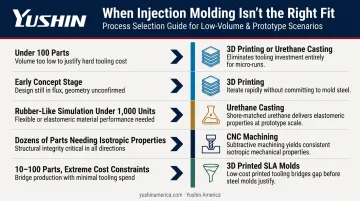
| Situation | Better Alternative |
|---|---|
| Under 100 parts | 3D printing or urethane casting |
| Early concept stage, geometry still evolving | 3D printing — no tooling commitment |
| Rubber-like material simulation under 1,000 units | Urethane casting |
| Dozens of parts, isotropic properties required | CNC machining from plastic billet |
| 10–100 parts, extreme cost constraints | 3D printed molds (SLA resin) — expect reduced surface quality and short mold life |
A 2024 Formlabs analysis found that at 1,000 parts, 3D printing cost 85% less than injection molding in one documented comparison. At quantities where injection molding seems like the obvious choice, it frequently isn't.
The Default-Process Warning
If your team is running 50-part batches through injection molding because "that's how we always do it," the tooling cost per part cannot be justified. Before committing to any mold, compare injection molding against 3D printing, urethane casting, and CNC-machined plastic. That comparison takes an hour. Skipping it can cost thousands.
Frequently Asked Questions
How much does a small injection mold cost?
Mold costs range broadly — Formlabs estimates from roughly $100 for a 3D printed low-volume mold to $100,000+ for a complex multi-cavity steel tool. Simple aluminum single-cavity molds for low-volume runs typically fall in the $1,000–$10,000 range; soft steel molds with more complexity run higher. Part complexity, cavity count, surface finish, and whether you use MUD inserts (which eliminate the mold base cost) are the primary cost drivers.
What is the minimum quantity for injection molding?
There's no absolute minimum, but injection molding typically becomes cost-justifiable starting around 100 parts, where tooling costs begin to amortize across the run. Below that threshold, 3D printing or urethane casting almost always delivers lower total cost per part — especially when part geometry may still evolve.
What is micro-injection molding?
Micro-injection molding is a specialized process for extremely small plastic components, using modified machines with tighter tolerances. It's defined by part and feature scale (feature dimensions from 0.5 to 1,000 microns), not production volume — making it distinct from small scale injection molding, which refers to low-volume production of standard-sized parts.
What materials work best for low-volume injection molding?
Commodity resins — ABS, polypropylene, polyethylene — are common for low-volume runs due to processing flexibility and lower cost. Engineering resins like nylon, polycarbonate, and PEEK are used when end-use performance demands it. Material choice directly affects mold wear: glass-filled and mineral-filled grades are abrasive and accelerate aluminum tooling degradation, making soft steel a better mold material choice for those compounds.
Can I injection mold parts using 3D printed molds?
Yes, for very limited quantities. SLA resin molds can typically handle roughly 10–100 shots depending on injection pressure and resin material. They wear quickly, cannot achieve the tolerances or surface finish of machined metal tools, and suit concept validation rather than production-intent parts. For anything requiring dimensional accuracy or production-equivalent material performance, machined aluminum or steel tooling is necessary.