Key Takeaways
- Thin wall injection molding is defined by wall thickness typically below 1 mm and a flow-length-to-wall-thickness (L/T) ratio of 150:1 or greater — both criteria matter.
- The process demands higher injection speeds and pressures, hardened-steel molds, and a narrower process window than conventional molding.
- Polypropylene dominates material selection; high melt flow rate is the primary requirement across all suitable polymers.
- Short shots, warping, weld lines, and sink marks all trace back to specific design or process failures — and all are preventable.
- Cycle times can fall below 5 seconds for the thinnest packaging parts, making high-speed automated part removal a production requirement.
What Is Thin Wall Injection Molding?
Thin wall injection molding is a specialized form of injection molding producing plastic parts with wall thicknesses generally below 1 mm and a flow-length-to-wall-thickness (L/T) ratio of 150:1 or greater. Xometry defines this L/T threshold as the stronger processing criterion — ENGEL notes that production packaging applications regularly push flow path-to-wall ratios to 300:1 or 400:1.
Wall thickness alone doesn't tell the full story. A larger part with 1.5 mm walls can present identical thin-wall filling challenges if the flow path is long enough — what determines difficulty is whether the melt can travel the full cavity length before the solidified skin layer closes off flow.
What the Process Delivers
The goal is high-volume plastic parts that are:
- Lighter and more material-efficient than conventionally molded equivalents
- Produced at faster cycle times (thinner walls cool more quickly)
- Competitive on cost-per-part in high-output production environments
How It Differs from Conventional Injection Molding
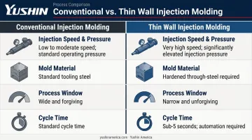
Conventional molding tolerates thicker walls, slower fill speeds, and a wider range of process parameters. Thin wall molding is unforgiving by comparison:
- Injection speed and pressure must be considerably higher to fill the cavity before freeze-off
- Molds must be built from hardened through-steels, not standard tooling grades
- The acceptable range of process parameters — temperature, pressure, speed, cooling time — is far narrower
- Cycle times are shorter, which demands automation at the press
Why Manufacturers Use Thin Wall Injection Molding
The business case is straightforward. For high-volume plastic part production, three factors compound into a meaningful cost advantage:
- Less material per part
- Faster cycle times
- Higher output per machine hour
Market Scale
The thin wall packaging market reached $51.16 billion in 2026, according to Mordor Intelligence, with injection molding accounting for 55.05% of production methods and polypropylene holding 42.65% of material share. Food and beverage packaging is the strongest documented end market — containers, lids, cups, and dairy tubs are the most common thin wall products.
Industries That Rely on It
| Industry | Typical Applications |
|---|---|
| Food & consumer packaging | Yogurt tubs, deli containers, beverage cups |
| Automotive | Interior trim panels, door inserts |
| Medical disposables | Syringe barrels, diagnostic trays, housing components |
| Consumer electronics | Device enclosures, connector housings |
The Lightweighting Driver
The U.S. Department of Energy reports that a 10% reduction in vehicle weight can improve fuel economy by 6–8%. That pressure on automotive suppliers to reduce component mass extends directly into thin wall molding adoption for interior plastic components. Sustainability requirements in packaging reinforce the same trend — lower polymer volume per unit cuts both material cost and carbon footprint per part produced.
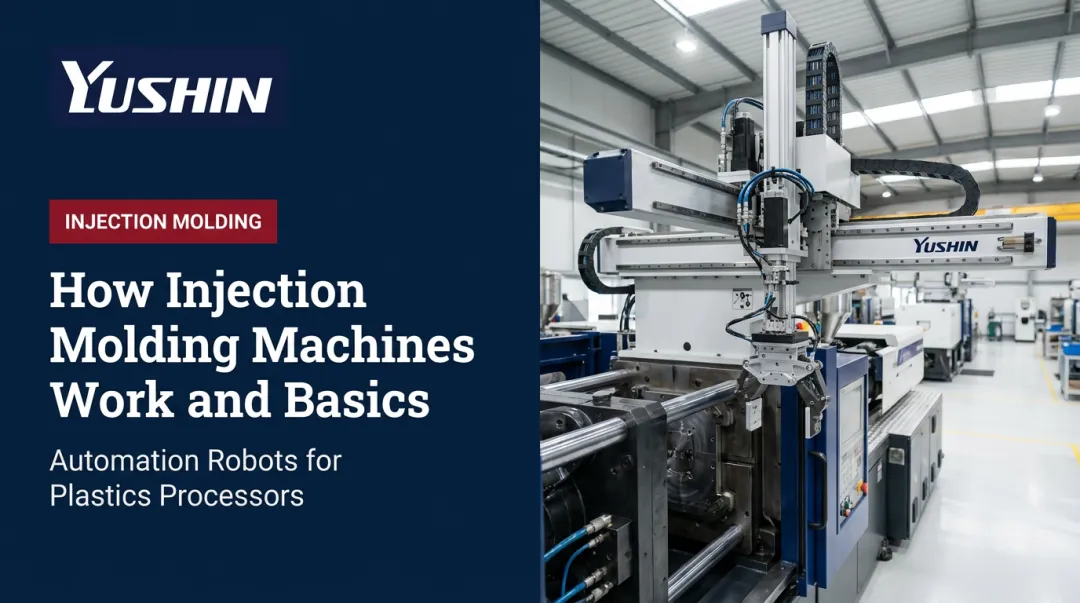
How Thin Wall Injection Molding Works
The basic sequence — melt, inject, cool, eject — applies here as it does in conventional molding. What changes is the physics governing each step.
The Solidified Skin Problem
As melt enters a thin cavity, it contacts the cool mold surface and immediately begins solidifying. This frozen skin layer grows inward from both walls, narrowing the effective flow channel. Research published in Materials & Design confirms that high-speed injection fills the cavity before this skin layer thickens enough to obstruct core flow — which is why injection speed is the primary lever in thin wall processing, not just injection pressure.
If the melt slows, or if the injection system hesitates, the skin layer wins. The result is a short shot.
Material Preparation and Injection
Resin pellets are heated and plasticized in the barrel to a precise melt temperature. The melt is then injected at high speed and pressure — Sumitomo Demag publishes injection speeds of 650 mm/s for thin wall applications and 1,000 mm/s for very thin wall, with injection pressures ranging from 148 to 289 MPa (approximately 21,500 to 41,900 psi). Materials must have sufficient melt flow rate to respond reliably at these conditions.
Mold Filling and Cooling
The mold — hardened tool steel with precision-placed gates, runners, and cooling channels — controls both fill behavior and solidification. Cooling channel placement close to the cavity surface is non-negotiable: heat must be extracted quickly and uniformly. Any imbalance in cooling translates directly to warping or dimensional variation in the finished part.
Ejection and Part Removal
Once solidified, the part is ejected. At cycle times of 3 to 12 seconds for high-performance packaging applications, manual part removal is physically impractical — it introduces inconsistent grip force, risks part deformation from extended mold contact, and breaks cycle continuity.
High-speed take-out robots are the standard solution. Yushin America's robot lineup covers the full speed range thin wall processing demands:
- HST series — demonstrated a 0.5-second extraction time for an 8-cavity thin wall medical part running a 3-second molding cycle at NPE 2018
- HSA super-high-speed robots — tuned for sub-5-second packaging cycles with the highest cavitation counts
- TSXA side-entry robots — target sub-3-second cycles in IML packaging cells, placing labels and extracting parts in a single mold-open pass
Design Considerations for Thin Wall Injection Molding
Getting the process right starts before the mold is built. Design decisions made early determine whether the part fills cleanly, ejects without damage, and holds dimensions in production.
Wall Thickness and Uniformity
Consistent wall thickness throughout the part is the most fundamental design rule. Uneven walls cool at different rates, generating internal stress that causes warping and dimensional variation.
- Target uniform thickness across all sections of the part
- Where ribs are required, keep rib thickness at 50–60% of the nominal wall to prevent sink marks at the rib base
- Avoid abrupt thickness transitions — taper transitions gradually where geometry requires them
Gate Placement and Runner Design
Gate location controls where the melt front starts and how it travels. Poor gate placement creates:
- Longer-than-necessary flow paths that increase freeze-off risk
- Weld lines positioned at structurally critical zones
- Air traps at cavity extremities
- Unbalanced fill across multi-cavity tools
For thin wall parts with large or complex cavities, multiple gates or hot runner systems are typically required to achieve even, fast fill. Gate sizing must also be sufficient to deliver adequate pack pressure throughout filling.
Mold Venting
At high injection speeds, air in the cavity has very little time to escape. Without vents deliberately placed at the last points to fill and at likely weld line locations, the consequences are:
- Short shots at cavity extremities
- Burn marks from compressed, overheated air
- Surface defects and cosmetic failures
Thin wall molds require more venting than conventional tools — faster fill leaves less time for air displacement, so vent count and placement deserve the same engineering attention as gating.
Draft Angles and Ejection
Adequate draft on vertical walls lets parts release cleanly during ejection. Insufficient draft combined with high injection pressure causes pull marks, surface whitening, or part distortion.
Internal sharp corners compound ejection stress by concentrating load at the worst possible point. Use corner radii wherever geometry allows — they improve material flow during filling and increase part strength after ejection.
Mold Construction and Tooling Requirements
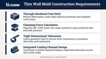
Thin wall molds are built to a different standard than general-purpose tooling:
- Through-hardened tool steel — softer mold materials wear rapidly under the high clamping forces and repeated high-pressure cycles that thin wall production demands
- Calculate clamping force per part using projected area multiplied by plastic pressure — packaging applications commonly require presses in the 150 to 1,000 metric ton range
- Tight dimensional tolerances at every mold interface — any slack in construction leads to flash, dimensional drift, or accelerated wear
- Cooling channel design integrated from the start, not retrofitted after tooling is cut
Common Defects in Thin Wall Injection Molding and How to Prevent Them
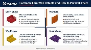
Short Shots
The most characteristic thin wall defect. The melt solidifies before the cavity is full, leaving an incomplete part.
Causes: Insufficient injection speed or pressure, premature skin-layer closure, inadequate melt temperature, undersized gates, poor venting.
Prevention:
- Increase injection speed first — this is the primary corrective lever
- Verify melt temperature is within the resin's processing window
- Check gate size and location; resize if flow analysis indicates restriction
- Inspect venting at cavity extremities for blockage or inadequate depth
Warping and Dimensional Distortion
Uneven internal stresses cause the part to distort after ejection. Large-area or slender parts are most vulnerable.
Causes: Non-uniform cooling, asymmetric wall thickness, unbalanced shrinkage across the part.
Prevention:
- Optimize cooling channel layout for uniform heat extraction across the entire cavity
- Enforce consistent wall thickness in the design; don't rely on process adjustment to compensate for geometry errors
- Adjust holding pressure and time to balance packing; validate with simulation before committing to tool modifications
Weld Lines and Structural Weakness
Weld lines form where two melt flow fronts meet inside the cavity. The junction is mechanically weaker than the surrounding material because polymer chains don't fully intermesh at a low-angle meeting.
In thin wall parts, this risk is amplified. The reduced cross-section already limits load-bearing capacity, and a weld line in a stressed zone can become a failure point.
Causes: Multiple gate locations, flow obstacles (cores, holes), or complex geometry that forces melt fronts to converge before the cavity fills.
Prevention:
- Reposition gates to redirect weld lines away from high-stress areas
- Increase melt and mold temperature to improve molecular diffusion at the weld interface
- Use flow simulation before tool build to predict weld line location and adjust gate strategy accordingly
Sink Marks, Shrinkage, and Surface Defects
Sink marks appear where uneven wall thickness, typically behind ribs, bosses, or standoffs, causes differential cooling and localized shrinkage.
Prevention:
- Keep rib thickness at 50–60% of nominal wall; avoid thick intersections
- Increase holding pressure and extend holding time to compensate for volumetric shrinkage
- Verify that the runner and gate system delivers adequate pack pressure to the full extent of the part; undersized runners bleed off pressure before the cavity is fully packed
Frequently Asked Questions
What is thin wall injection molding?
Thin wall injection molding produces plastic parts with walls typically below 1 mm and a flow-length-to-wall-thickness ratio of 150:1 or greater. The core challenge is filling the mold cavity before the solidified skin layer closes off flow — which demands higher injection speeds and pressures than conventional molding.
What is the minimum wall thickness for thin wall injection molding?
The threshold depends on part size and material. Walls below 1 mm typically qualify, with some packaging containers achieving walls below 0.62 mm with L/T ratios above 200. The definition is relative: a larger part with 1.5 mm walls can present the same filling challenges if the flow path is long.
How does thin wall injection molding differ from conventional injection molding?
Thin wall molding requires significantly higher injection speed and pressure, a narrower process window, hardened-steel molds built to tighter tolerances, faster cycle times, and materials with higher melt flow rates. Conventional injection molding equipment and mold designs are not built to handle these conditions reliably.
What materials are best suited for thin wall injection molding?
Polymers with high melt flow rates perform best: polypropylene (PP), ABS, polycarbonate (PC), nylon (PA), and polyethylene (PE). Highly filled or fiber-reinforced grades increase melt viscosity and should be validated with flow simulation before committing to a thin wall design.
What are the most common defects in thin wall injection molding?
Short shots (insufficient fill speed or pressure), warping (uneven cooling), weld lines (poor gate placement or low melt temperature), and sink marks (wall thickness variation and inadequate packing pressure) are the four most frequent defects — each traceable to specific design or process failures.
What are the alternatives to thin wall injection molding?
Common alternatives include conventional injection molding (thicker-walled parts), gas-assisted molding (hollow internal structures), foam injection molding (weight reduction via foamed core), and thermoforming (large thin-gauge sheet products). The right choice depends on part geometry, production volume, and performance requirements.