Neither is random. Both are deliberate programming choices, and selecting the wrong one in the wrong place can mean a slower cycle, a damaged mold, or a dropped part.
This article explains what linear and joint motion commands are, how they differ mechanically, and why the distinction matters for anyone programming or optimizing injection molding take-out automation.
Key Takeaways
- Linear (LIN) motion moves the robot's TCP in a straight line — essential near mold faces and tooling
- Joint (PTP) motion is faster, follows a non-linear path, and is ideal for open-space travel between positions
- Arc/circular motion handles constant-radius curved paths, with limited use in injection molding compared to LIN and PTP
- Choosing the right motion type determines cycle time, path safety, and part quality
- In injection molding, matching motion type to each phase of extraction reduces cycle time and prevents mold contact
What Are Robot Motion Types?
Most robot controllers provide three core motion commands. Each tells the robot not just where to move, but how to get there — and that distinction carries real consequences.
| Motion Type | Command Names | Path Behavior |
|---|---|---|
| Linear | LIN, MoveL | TCP follows a straight line |
| Joint / Point-to-Point | PTP, MoveJ | Fastest path, generally not straight |
| Arc / Circular | CIRC, MoveC | TCP follows a constant-radius curve |
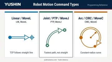
Linear and joint are the workhorses of everyday automation. Arc motion is specialized — primarily used in welding and finishing applications — and rarely appears in injection molding automation.
The Role of Coordinate Frames
Where a robot moves depends entirely on which coordinate frame it's referencing. Most controllers recognize three: a base frame (anchored to the robot's mounting position), a tool frame (centered on the TCP), and a work or part frame (aligned to the fixture or mold). ABB's coordinate system documentation outlines how the robot resolves its TCP position within this frame hierarchy.
Selecting the wrong frame can send the robot to a completely unintended location. In a confined space like an injection mold, that means a collision — and potential mold damage.
Understanding Linear Motion in Robotics
What Linear Motion Is and How It Works
Linear motion (called MoveL in ABB's RAPID language and LIN in KUKA's KRL) commands the robot's TCP to travel in a perfectly straight line from its current position to the destination. According to the ABB RAPID technical reference manual, MoveL moves the robot linearly, with the TCP following a straight-line path throughout the move.
To maintain that straight path, all joints must rotate simultaneously and in coordination. The controller continuously recalculates joint positions to keep the TCP on the exact programmed line. Speed for linear motion is measured in mm/s — a unit that reflects its path-controlled nature, not a percentage of any individual joint's capacity.
When to Use Linear Motion
Linear motion is the right choice whenever the path itself matters, not just the destination:
- Entering or exiting a mold cavity : the robot must follow a predictable, controlled trajectory to avoid contact with mold faces, slides, or lifters
- Approach and retract moves near tooling or fixtures : any position where an unexpected arc could mean a collision
- Precision operations : welding, cutting, dispensing, or gluing where path deviation causes defects or waste
Limitations of Linear Motion
Speed is the core trade-off. Because all joints must coordinate to maintain the straight-line path, linear motion is generally slower than joint motion, particularly over longer distances.
Singularity risk is the other consideration. When an articulated robot approaches certain configurations (such as a fully extended arm or specific joint alignments), maintaining a strict Cartesian path can force one or more joints toward extreme velocity changes. FANUC Tech Transfer defines singularity as a condition where the robot has an infinite number of kinematic possibilities to reach the same end position and may fault if it cannot select a solution. ABB's community resources specifically flag MoveL as a command that requires singularity validation before deployment.
For Cartesian take-out robots like Yushin's servo-driven traverse systems, this concern is less acute — their straight-axis design avoids the rotary-joint singularity problem common to six-axis arms.
Understanding Joint Motion in Robotics
What Joint Motion Is and How It Works
Joint motion (MoveJ in ABB, or PTP meaning point-to-point in KUKA) moves the robot from one position to another by letting each joint rotate at its own optimized speed. No coordination is imposed to maintain a straight TCP path.
KUKA's KSS 8.3 programming documentation describes PTP as moving the TCP along the fastest path, which is generally not a straight line. Speed is programmed as a percentage of maximum axis velocity (1–100%), not in mm/s. Because joints can each run at their maximum rate without coordinating, PTP is the fastest way to move between two positions.
When to Use Joint Motion
Joint motion excels when only the destination matters and the space between is clear:
- Traveling from home position to a pounce/approach point above the work area
- Moving between stations in open, unobstructed space
- Any repositioning move where intermediate path shape carries no risk
As long as positions and speeds stay constant, joint motion follows the same path every cycle — repeatable and predictable when programmed correctly.
That said, KUKA's documentation notes that changing speed or acceleration settings can alter the PTP path. Re-verifying clearances after any speed adjustment is essential during commissioning.
Limitations of Joint Motion
The path is not a straight line and is not intuitively readable from the programmed positions alone. A robot executing a joint move may swing wider or narrower than expected, depending on configuration.
Joint motion should never be used:
- Near mold faces, slides, or ejector mechanisms
- In confined spaces where unexpected arcing could contact guarding or tooling
- Anywhere personnel could be within the robot's swing envelope
Terminology clarification: A "linear joint" or prismatic joint is a physical hardware mechanism — a sliding joint that moves along a single axis, common in Cartesian/gantry robots.
This is architecturally distinct from a "linear motion" command, which is a programming instruction. The two terms sound similar but refer to completely different things.
Linear vs. Joint Motion: Key Differences and When to Use Each
For every move in a robot program, the core question is: does the path matter, or only the destination?
If the path matters — use linear. If only the destination matters and space is clear — use joint.
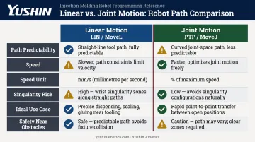
| Attribute | Linear (LIN / MoveL) | Joint (PTP / MoveJ) |
|---|---|---|
| Path predictability | TCP follows a straight line | Path is not a straight line; varies with speed |
| Speed | Slower; joints must coordinate | Faster; each joint moves at optimal speed |
| Speed unit | mm/s | % of maximum axis speed |
| Singularity risk | Yes — especially on articulated arms | Lower, but clearance must still be verified |
| Ideal use case | Mold entry/exit, approach, precision ops | Home-to-pounce, open-space repositioning |
| Safety near obstacles | High — path is known and controlled | Low — intermediate path must be verified |
How the Two Motion Types Work Together
In practice, most robot programs blend both types. A take-out robot executing a typical extraction cycle might:
- Joint move — fast arc from home position to pounce point above the mold
- Linear move — controlled descent into the mold cavity to grip the part
- Linear move — careful retract out of the mold, following the same straight path in reverse
- Joint move — high-speed transfer to the conveyor or downstream station
That alternating pattern is what enables both throughput and mold protection within the same cycle.
Arc / Circular Motion
A third motion type worth knowing: arc motion (MoveC in ABB, CIRC in KUKA) commands the TCP along a constant-radius curved path. Key characteristics:
- Requires three defined points — a start position, a midpoint along the arc, and an endpoint
- If the robot begins a circular move with the TCP already between the midpoint and endpoint, it may travel in an unintended direction (per ABB's RAPID manual)
- Welding, painting, and finishing cells use arc motion routinely — standard injection molding extraction does not
Motion Type Selection in Injection Molding Automation
The Practical Stakes
In injection molding, the take-out robot's cycle time is inseparable from the machine's overall cycle time. The robot must enter the mold, grip the part, and retract before the mold closes — and it needs to be in position before mold opening begins to eliminate waiting time. A 2016 Plastics Technology article warns that excessive cycle optimization can produce out-of-spec parts, meaning speed and precision must be balanced, not traded against each other.
The split between joint and linear motion is one of the key levers in that balance.
Typical Motion Sequence for a Take-Out Robot
Here's how motion type selection maps to a standard extraction cycle:
- Joint motion — robot travels from home to the mold approach (pounce) position at maximum speed through open air
- Linear motion — controlled entry into the mold cavity along a straight, predictable path
- Linear motion — straight retract out of the mold, maintaining the same controlled trajectory
- Joint motion — fast transfer to the conveyor, downstream fixture, or parts deposit position
Each transition serves a purpose: joint moves protect cycle time, linear moves protect the mold.
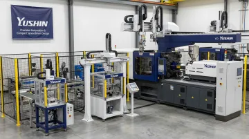
Yushin's Take-Out Robots
Yushin's servo-driven take-out robots are built around this precision-speed tradeoff. Key models and their cycle performance:
- HSA series — achieves take-out times of 0.27 seconds in actual molding conditions, roughly 25% shorter than predecessor models
- FRA series — Yushin's flagship line with Active Vibration Control and INTU LINE IoT monitoring, reducing take-out cycles by up to 29% versus previous generations
- YD-0310 Servo Picker — compact 3-axis AC servo system for 30–150 ton press cells, with sub-one-second take-out and a low-vibration arm design suited for medical, electronics, and consumer parts
For application-specific guidance on programming motion sequences and optimizing cycle time for your mold configuration, contact Yushin America's engineering team directly — their application engineers can walk through extraction cycle motion planning for specific robot models and controller configurations.
Frequently Asked Questions
What is a linear joint in robotics?
A linear joint (also called a prismatic joint) is a physical robot joint that allows sliding movement along a single axis — it's a hardware mechanism. "Linear motion," by contrast, is a software command that controls how the robot's TCP travels through space — the two terms describe fundamentally different things.
What are the different types of joints in robots?
The standard joint types are revolute (rotary), prismatic (linear/sliding), cylindrical, spherical, and universal. Most industrial robot arms are built primarily from revolute joints, while Cartesian and gantry robots use prismatic joints arranged along perpendicular axes.
What is the difference between linear and orthogonal joints in robots?
An orthogonal (Cartesian) robot uses prismatic joints along perpendicular X, Y, Z axes to produce purely linear movement along each axis. In revolute-joint robots, motion comes from angular rotation rather than sliding, so the term "linear joint" applies specifically to the prismatic sliding joints found in Cartesian systems.
What is the difference between linear (LIN) and PTP motion in robots?
LIN commands the TCP to follow a straight-line path between two points with full path control. PTP moves each joint independently to reach the destination without constraining the intermediate path. PTP is faster, but the TCP does not travel in a straight line between points.
When should a robot use linear motion vs. joint motion?
Use linear motion when the path matters — entering confined spaces, approaching tooling precisely, or performing path-sensitive operations. Use joint motion when only the destination matters and the robot is moving through open, unobstructed space, as it is significantly faster and helps reduce cycle time.
What is arc motion in robotics and when is it used?
Arc (circular) motion commands the TCP to follow a constant-radius curved path, defined by a start point, a midpoint along the arc, and an endpoint. Welding, painting, and finishing operations use it most often, as those processes require smooth, continuous curved movement along the workpiece.