Introduction
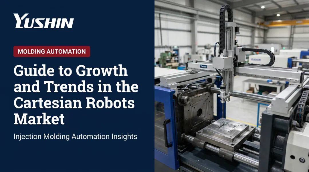
Cartesian robots are among the most widely deployed systems in industrial automation — yet "Cartesian robot" covers a surprisingly broad range of structural designs. Pick the wrong one and you're looking at cycle time bottlenecks, payload limits, or a footprint that doesn't fit your cell.
Choosing the wrong configuration upfront isn't just a technical inconvenience. It shows up as cycle time plateaus, part damage from underpowered axes, or expensive retrofits when a robot can't reach far enough or carry enough load. According to McKinsey's 2020 Industry 4.0 manufacturing report, broad automation deployment can reduce cost-of-quality by 10% to 20% in discrete manufacturing — but only when the right systems are in place.
This article breaks down the three primary Cartesian robot configurations — standard 3-axis, gantry, and 2-axis — covering how each is structured, where each fits, and what to evaluate before committing to one.
Key Takeaways
- Precision and repeatability define Cartesian robots — they move along orthogonal X, Y, and Z linear axes with highly predictable motion
- Standard 3-axis, gantry, and 2-axis configurations differ fundamentally in structural layout, payload, and reach
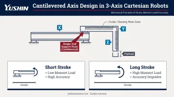
- Cantilevered axis design limits payload and stroke on standard 3-axis systems — a commonly overlooked constraint
- Gantry robots free up overhead floor space and handle longer strokes and heavier loads through dual-axis support
- Configuration selection should be driven by payload, cycle time, stroke, and facility layout — not cost alone
What Is a Cartesian Robot?
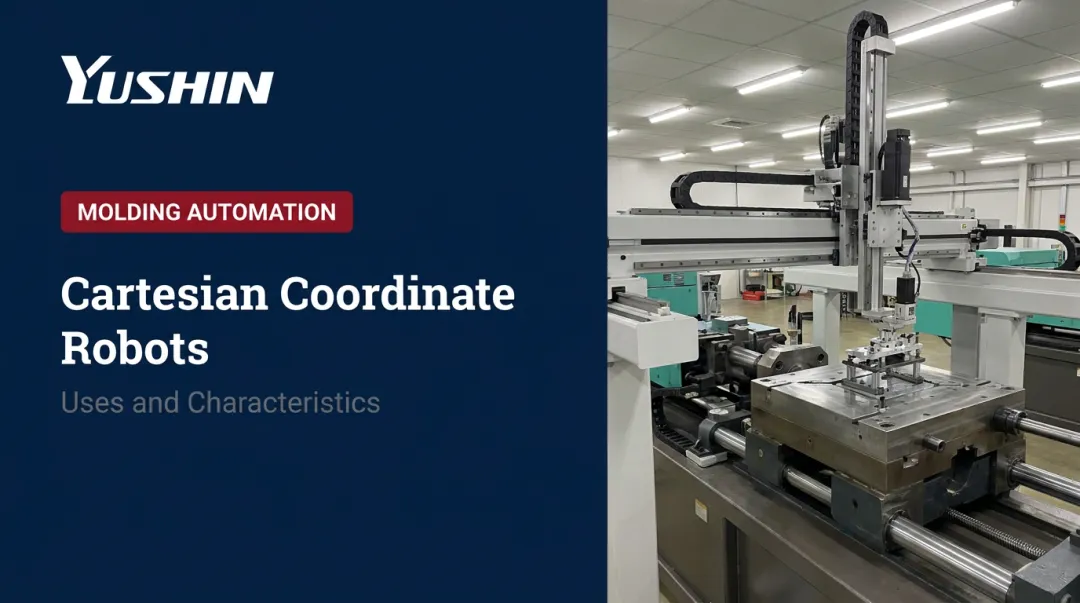
A Cartesian robot is an industrial manipulator that moves its end effector along three orthogonal linear axes (X for horizontal traverse, Y for vertical or cross-mold, and Z for depth or in/out), using the Cartesian coordinate system as its motion framework. A rotary end effector can be added as a fourth axis for applications requiring part reorientation.
What distinguishes a Cartesian system as a robot rather than a collection of actuators is coordinated, programmable motion via a shared motion controller. Each axis responds to a unified program, not independent commands. That shared control is what makes repeatable, automated cycles possible.
Where Cartesian Robots Are Used
Cartesian robots appear across a wide range of manufacturing and processing environments:
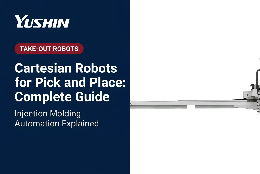
- Plastic injection molding — part take-out and sprue removal
- CNC machine tending — loading and unloading machined parts
- Assembly and dispensing — precise positional control in defined work envelopes
- Packaging and palletizing — repetitive pick-and-place on flat or layered planes
- Electronics manufacturing — insertion, testing, and handling of small precision parts
That breadth of application reflects real market scale. The Cartesian robot market is estimated at USD $3.4 billion in 2025, with three-axis configurations alone accounting for roughly 29.7% of product-segment value.
Key Cartesian Robot Configurations and Types
"Cartesian robot" describes a family of configurations, not a single product type. They differ in how axes are supported, how loads are distributed, and what work envelope shapes they can cover.
Choosing between them comes down to matching structural design to the specific demands of the application.
Standard 3-Axis Cartesian Robot
A standard 3-axis Cartesian robot uses one linear actuator per axis — X, Y, and Z — with the secondary and tertiary axes cantilevered: supported only at one end by the axis beneath them.
That cantilevered design creates moment loads on the guide system. As stroke length increases or payload grows, those loads compound, reducing positioning accuracy and accelerating wear on bearings and guides. Bosch Rexroth's linear guide documentation is direct on this point: combining forces and moments decreases expected service life, and an undersized runner block at a combined load ratio above 0.4 is structurally insufficient for the application.
Best suited for:
- Moderate payloads (up to roughly 78 kg at compact scale, per IAI's catalog specifications)
- Shorter stroke lengths where cantilever deflection is manageable
- Assembly, dispensing, CNC machine tending, and light pick-and-place tasks
- Facilities with limited floor space and predictable payload demands
Key trade-offs:
| Strength | Limitation |
|---|---|
| Cost-effective | Cantilever loads cap payload and stroke |
| Simple programming | Scaling outer axis adds structural risk |
| Compact footprint | Not suited for long-reach, heavy-duty tasks |
| High precision at moderate loads | Accuracy degrades as stroke extends |
In injection molding, Yushin America's top-entry traverse robots — including the YD/YD2 Series (5–15 kg, 50–850 ton presses), HST high-speed robots, and the large MKA-2000S (30–80+ kg, up to a 5,000 mm traverse beam) — all use 3-axis Cartesian configurations with AC servo-driven X, Y, and Z axes.
As payload and reach grow, Yushin engineers progressively into reinforced structures: oversized linear guides, high-torque servos, and telescopic arms that counter the deflection risks inherent to extended cantilever reach.
Gantry Robot (Overhead Bridge Configuration)
A gantry robot replaces the single base axis of a standard Cartesian system with two parallel base (X) axes, connected by a bridging Y axis. That Y axis is supported at both ends rather than cantilevered — eliminating the moment loading problem that limits standard designs.
Parker's gantry System 1 uses two HLE linear modules linked by a common drive shaft, with the Y axis bridging them. System 2 adds a second Y-axis module as an idler, further increasing moment load capacity and permitting longer travel — up to 7.9 m on the X axis and 200 kg maximum load. Güdel's CP 3-axis gantry supports strokes up to 100,000 mm on X with repeatability of ±0.02 mm.
Because the robot operates overhead, the floor space beneath the work envelope remains free — a direct operational gain in busy production cells.
Best suited for:
- High-payload, long-stroke applications where cantilever designs would fail
- Injection molding part take-out from large-tonnage presses
- Palletizing and material transfer across wide work cells
- Overhead part handling where floor space beneath the robot must stay clear
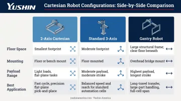
These three configurations — standard 3-axis, gantry, and 2-axis — cover the majority of Cartesian robot installations. Understanding which structural form fits your payload, stroke, and spatial constraints is the starting point for any specification decision.
How to Choose the Right Cartesian Robot Configuration
Configuration selection comes down to four application variables: payload, cycle time, work envelope, and environment. Getting the match right the first time avoids costly retrofits or replacements down the line.
Payload and Stroke Length
Payload is the first filter. If the combined weight of the part plus end-of-arm tooling sits within a standard 3-axis robot's capacity — and stroke length is short enough that cantilever deflection won't degrade accuracy — a standard design works.
When payload climbs or stroke extends significantly, moment loads on cantilevered axes become the governing constraint.
Bosch Rexroth documents that linear axes with dual guide rails can move up to 220 kg over lengths up to 10 m under high transverse forces — a structural capability only available in fully supported (gantry) configurations. For high-payload, long-reach applications, that structural difference is decisive.
Cycle Time and Speed Requirements
- 2-axis systems cycle fastest on flat-plane tasks — no Z-axis movement to sequence
- Standard 3-axis robots balance spatial flexibility with speed; high-speed variants (like Yushin's HST and HSA series) target sub-10-second and sub-5-second cycles respectively
- Gantry configurations carry higher structural mass, which limits peak acceleration, but their rigidity sustains consistent speeds under heavy loads — run a cycle time comparison against your production targets before committing
Once speed requirements are mapped, the work envelope determines which configuration physically fits the cell.
Work Envelope and Floor Space
| Configuration | Floor Space Impact | Mounting |
|---|---|---|
| 2-axis Cartesian | Smallest footprint | Floor or bench |
| Standard 3-axis | Moderate footprint | Floor-mounted |
| Gantry | Large structural footprint, but floor beneath is free | Overhead structure required |
Application Environment
For plastic injection molding, gantry-style top-entry traverse robots dominate because overhead access is required for mold clearance and part extraction — and because the payload and reach demands of mid-to-large tonnage presses exceed what cantilevered standard designs can reliably handle.
For electronics assembly, lab automation, and light pick-and-place, standard 3-axis or 2-axis configurations are the practical choice. Lower payloads, tighter footprints, and faster cycle requirements all favor the lighter, simpler architecture.
Common Mistakes to Avoid When Selecting a Cartesian Robot Configuration
Choosing Based on Cost Alone
A 2-axis or standard 3-axis robot costs less upfront. If the application actually requires gantry-level payload or stroke, that initial saving disappears quickly — absorbed by downtime, part damage, premature equipment failure, and retrofit costs. Automation.com identifies payload underestimation as one of the top mistakes in robotics application specification, noting that end-of-arm tooling weight, part weight, and cable dress all affect the real payload demand on the system.
Ignoring Cantilevered Axis Limitations
Side-load capacity on cantilevered axes decreases as the extension tube extends — and published specifications are typically valid only at full retraction. Many buyers don't account for how moment loads scale with stroke length and payload. The result is accelerated bearing wear and lost positioning accuracy well before expected service life.
Key factors that compound cantilevered load errors:
- End-of-arm tooling weight at full extension
- Payload mass combined with acceleration forces
- Cable dress routing that adds unplanned side loads
- Stroke length mismatched to the actual retracted-position spec
Treating All Cartesian Robots as Interchangeable
A standard 3-axis Cartesian robot and a gantry robot are not the same system with different price tags. They have different structural designs, load capacities, and installation requirements. Treating a gantry as simply a larger standard Cartesian during procurement leads to undersized installations and costly re-engineering once the application is running.
Conclusion
Cartesian robots span a family of structurally distinct configurations, each built around different axis support designs and load mechanics. Standard 3-axis designs serve moderate payload and stroke applications well. Gantry configurations handle long-reach, high-payload tasks that cantilevered designs cannot sustain. Two-axis systems cover flat-plane applications efficiently where a third axis adds no value.
The difference between a well-matched automation deployment and a costly mismatch comes down to understanding axis support design, load mechanics, and work envelope requirements before a purchase order is placed. Nail those three decisions upfront, and robot selection, integration, and long-term reliability fall into place — rather than becoming problems to solve after installation.
Key selection factors to confirm before specifying a configuration:
- Axis support type — cantilevered vs. dual-supported, based on payload and stroke length
- Work envelope shape — rectangular reach requirements vs. flat-plane coverage
- Load mechanics — moment loads at full extension, not just rated payload at center
Frequently Asked Questions
What is the structure of a Cartesian robot?
A Cartesian robot consists of linear actuators arranged along orthogonal X, Y, and Z axes, each driven by a motor and guided by rails. A motion controller coordinates all axes simultaneously, moving an end effector to programmed positions with repeatable precision.
What are the four basic configurations of robots?
The four most commonly cited configurations are Cartesian (three prismatic linear joints), articulated (three or more rotary joints, like a human arm), SCARA (two parallel rotary joints for selective-compliance planar motion), and cylindrical (rotary plus linear movement forming a cylindrical coordinate system).
How much does a Cartesian robot cost?
Entry-level systems start low — igus lists an XY actuator at around $1,292 and a drylin XXL 3-axis gantry starting at $7,000 including controls. Industrial-grade systems are quote-based, with cost driven by axis count, stroke, payload, controls, end-of-arm tooling, and integration complexity.
What is the difference between a Cartesian robot and a gantry robot?
A standard Cartesian robot uses one base axis with the secondary axis cantilevered (supported only at one end). A gantry robot uses two parallel base axes that fully support the bridging axis at both ends, eliminating cantilever loads and enabling significantly longer strokes and higher payloads.
How many axes does a Cartesian robot have?
Most Cartesian robots operate on 2 linear axes (X/Y) or 3 linear axes (X/Y/Z). Some configurations add a rotary fourth axis via the end effector. Advanced systems — such as Yushin's FRA Series — can reach up to 8 controlled axes by combining the core Cartesian configuration with a multi-axis servo wrist unit.
What industries use Cartesian robots most commonly?
Plastic injection molding (part take-out), electronics assembly, packaging, CNC machine tending, and palletizing are the primary industries. Each relies on Cartesian robots for their positioning precision, repeatable cycle times, and simple programming across high-volume production environments.