Introduction
Demand for smaller, more precise components is accelerating across medical devices, electronics, and automotive systems. The problem is that conventional injection molding hits a wall at micro scale — standard machines lack the dosing precision, tooling accuracy, and process control needed to produce sub-gram parts with consistent dimensional integrity.
Micro injection molding addresses this directly. It's a specialized manufacturing discipline capable of producing components weighing less than one gram with tolerances as tight as ±0.0005 inches (roughly 12 microns), according to Plastics Technology.
These aren't simply "small" parts made on smaller machines. They require fundamentally different equipment, tooling expertise, material selection, and process engineering.
This guide covers what micro injection molding is, how the process works, the real benefits it delivers, where it's applied, and the challenges that demand specialized automation to solve.
Key Takeaways
- Micro injection molding produces parts weighing under one gram — sometimes less than 0.001 g — with tolerances measured in microns, far exceeding conventional molding capabilities.
- The process requires specialized machines, precision CNC/EDM tooling, and tightly controlled injection variables — conventional equipment won't cut it.
- Medical devices account for over 45% of the market, followed by electronics, optics, and automotive.
- Post-mold part handling and automation are just as critical as the molding step when scaling micro production.
What Is Micro Injection Molding?
Micro injection molding is a highly specialized subset of injection molding designed to manufacture extremely small thermoplastic components with micron-level tolerances. The critical distinction: it is not conventional molding scaled down. As MDPI Polymers research confirms, standard processing assumptions and measurement methods don't apply at this scale — rapid freezing from high thermal exchange between polymer and cavity surfaces fundamentally changes how the process behaves.
Three Definitions of "Micro"
The industry applies "micro" in three distinct ways:
- Micro part size — components weighing less than one gram, with features measured in millimeters or fractions thereof. Arburg's dedicated micro injection unit targets shot weights under one gram; WITTMANN's MicroPower 15 t handles shot weights from 0.05 to 4 grams.
- Microfeatures — tiny functional details (holes, ribs, threads) incorporated into a larger component
- Micro tolerances — precision requirements as tight as ±0.0001 inches on tool steel, yielding molded parts held to ±0.0005 inches
Real-world examples of what this looks like: Arburg has demonstrated production of 0.004 g PBT counting wheels (four parts in a 12-second cycle) and 0.009 g LSR caps for medical switches. Accu-Mold has produced alignment spacers measuring 800 µm × 380 µm × 360 µm, with 144,000 parts weighing just one ounce combined.
Materials That Matter
Small cavity volumes, thin walls, and ultra-short fill times make material choice critical in micro molding — more so than in conventional processing. Flow behavior and thermal stability directly affect whether a part fills, holds tolerance, or fails entirely. Common materials include:
- LCP (Liquid Crystal Polymer) — high-flow, excellent for thin-wall precision parts
- PEEK — biocompatible and chemically resistant; the go-to for medical and high-performance engineered components
- POM / Acetal / Delrin — preferred where dimensional stability and mechanical precision matter most
- Polycarbonate — optical clarity and impact resistance for medical and electronics applications
- PMMA — optical-grade applications requiring light transmission
What Makes a True Micro Molder
Equipment alone doesn't qualify a shop as a micro molder. What separates genuine micro molders is the combination of capabilities behind the machine:
- Specialized tool-building expertise for cavities at sub-millimeter scale
- Process engineering experience with the failure modes unique to micro-scale fill and cooling
- High-resolution metrology capable of verifying tolerances at ±0.0005 inches
- Accumulated production data from running these parts across real programs
Micro Injection Molding vs. Conventional Injection Molding
The differences between micro and conventional molding go well beyond part size.
| Factor | Micro Injection Molding | Conventional Injection Molding |
|---|---|---|
| Shot weight | Under 1 gram (as low as 0.004 g) | Typically 1 oz or more |
| Tooling tolerance | Tool steel held to ±0.0001 in | Larger tolerances acceptable |
| Gate size | ~0.003 in / 75 µm | ~0.020 in / 500 µm |
| Injection time | Often less than 0.1 seconds | Seconds to minutes |
| Injection pressure | 30,000–50,000 psi typical | Lower; application-dependent |
| Materials | High-performance specialty polymers | Broad thermoplastic range |
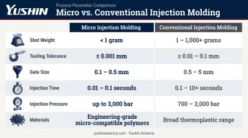
The gate size difference alone illustrates why micro molding is a distinct discipline. A 75 µm gate generates shear-heating effects that don't occur at 500 µm — and those shear effects directly influence material degradation, fill uniformity, and dimensional outcome.
Machine architecture is engineered around these melt-control demands. Arburg's micro injection unit pairs an 8 mm injection screw with a secondary plasticizing screw to ensure homogeneous melt and short residence time under first-in, first-out (FIFO) processing — a design built specifically for sub-gram shot control that conventional machines don't require.
How the Micro Injection Molding Process Works
Mold Design and Tooling Preparation
Precision molds for micro injection molding are machined using CNC and EDM techniques to tolerances measured in microns. To hold a molded part to ±0.0005 inches, the tool steel itself must be held to ±0.0001 inches — and some cavity radii fall below one micron. Every variable compounds at this scale.
Every design decision at this stage cascades downstream. Key tooling parameters include:
- Parting line alignment — microscale misalignment causes flash that's impossible to remove from sub-gram parts
- Gate location and runner sizing — determines fill behavior and shear heating at entry
- Venting geometry — insufficient venting traps air and causes short shots
- Demolding strategy — ejection forces that are negligible at macro scale can deform or destroy micro features
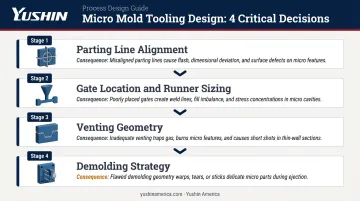
There's little margin for iteration once tooling is cut.
Material Preparation and Injection
A specialized micro injection unit melts and homogenizes the polymer and rapidly injects a precisely metered shot into the heated mold cavity. Key variables requiring tight control:
- Injection speed — high velocity needed to overcome hesitation caused by rapid thermal exchange
- Melt temperature — must balance flow requirements against residence time degradation risk
- Mold temperature — affects fill, surface replication, and cooling uniformity
- Gate geometry — directly affects shear heating and material behavior at entry
ASME research on micro injection filling confirms that resistance to air evacuation is a critical parameter affecting cavity fill behavior — something conventional molding largely ignores.
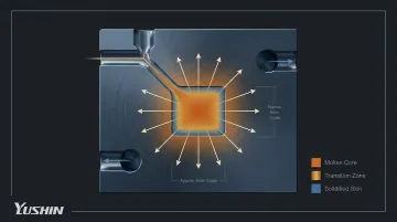
Cooling and Solidification
Cooling at micro scale is aggressive. ScienceDirect research on precision injection molding of micro components reports heat-transfer coefficients of approximately 8,500 W/m²K during packing and 6,300 W/m²K during cooling. MDPI research describes rapid freezing caused by high thermal exchange between the polymer and cavity surfaces.
Cooling must be fast enough for cycle efficiency but uniform enough to prevent warpage or dimensional variation. Non-uniform cooling — even across fractions of a millimeter — introduces residual stress that shifts critical dimensions outside tolerance. This physical state of the part as it leaves the cavity directly shapes the ejection challenge that follows.
Ejection, Degating, and Quality Control
Ejecting a part that weighs less than a gram without damage or displacement is not trivial. Approaches include direct gating (eliminating separate gate removal), valve gates, and overflow venting to ensure complete fill without creating gate remnants that complicate degating.
Quality inspection cannot be an afterthought. Standard micro-scale inspection methods include:
- High-resolution vision systems for dimensional verification
- Precision gage pins for bore and feature checks
- 3D laser scanning for full-surface geometry capture
- High-speed video to detect ejection anomalies in real time
Accu-Mold documents 100% inspection protocols, continuous inspection, and production audits as standard practice. A defect invisible to the naked eye can still render a medical component or precision optical part unusable.
Key Benefits of Micro Injection Molding
Precision and Repeatability at Scale
The primary advantage is the ability to reproduce complex geometries with micron tolerances across thousands or millions of parts consistently. CNC machining can achieve similar tolerances on individual parts, but cannot match micro injection molding's throughput or per-part cost at volume. High-volume micro applications routinely achieve inline testing in under two seconds per cycle — a benchmark that manual or semi-automated handling cannot sustain reliably.
Cost Efficiency for High-Volume Production
Tooling investment in micro molding is significant. But per-part costs drop substantially at volume for several reasons:
- Shorter cycle times than conventional parts
- Minimal material waste per shot
- Smaller machine footprints requiring less floor space
- Reduced clamping force requirements lowering machine operating costs
At sufficient volumes, per-part costs often drop to a fraction of what CNC or EDM-based alternatives require — which is why high-cavitation medical and electronics molders commit to micro tooling early in program development.
Design Consolidation and Miniaturization
Micro injection molding enables multiple functional features — bosses, threads, undercuts, optical surfaces — within a single micro-scale component. This reduces assembly steps, eliminates secondary operations, and enables product miniaturization that alternative manufacturing methods cannot achieve at comparable volumes.
Material Versatility
The process supports a wide selection of high-performance polymers that can be matched to specific functional requirements:
- PEEK and USP Class VI-compliant resins for implantable and drug-delivery components
- COC and optical-grade PMMA for lenses and light guides
- LCP and high-temperature nylon for electronics and automotive sensor housings
- PTFE-filled and chemically resistant grades for laboratory and diagnostic devices
The right material match is determined at the design stage — before tooling is cut — so that mechanical, regulatory, and processing requirements align from the start.
Industries and Applications of Micro Injection Molding
Medical and Healthcare
Medical accounts for over 45% of the micro injection molded plastics market as of 2024 — and the reasons are straightforward. Applications include:
- Drug delivery micro-components and syringe barrels
- Catheters and minimally invasive surgical instruments
- Implantable device components
- Microfluidic systems for diagnostics
- Hearing aid housings and components
- Medical switches and connectors (Arburg documents 0.009 g LSR caps for medical switches)
Dimensional accuracy in these applications directly affects patient safety and device performance. Even sub-micron deviations in a catheter tip or implantable connector can compromise function — which is why medical micromolding demands the tightest process controls in the industry.
Electronics and Optics
Consumer electronics and industrial applications drive demand for:
- Micro-connectors and micro-terminals
- MEMS (microelectromechanical systems) housings
- Optical fibers, lenses, prisms, and light guides
- Aspheric lenses with diameters as small as 100 microns
Aspheric lenses at 100-micron diameters and MEMS housings with sub-millimeter wall sections push part extraction and handling to their limits — making automation a practical requirement, not an optional upgrade.
Automotive, Aerospace, and Emerging Applications
Beyond electronics, micro molded components are embedded throughout vehicle systems, aerospace instrumentation, and connected devices:
- Sensors, switches, and precision electrical connectors in vehicle systems
- Flow meters (micro turbines overmolded with magnets, per Arburg documentation)
- Aerospace instrumentation housings
- Wearable devices and IoT sensors
Across all three sectors, part fragility and micron-level tolerances mean that consistent, automated part removal — using side-entry robots like Yushin's SXC series — is critical to maintaining yield and cycle integrity at production volumes.
Challenges in Micro Injection Molding and the Role of Automation
Tooling Complexity and Process Sensitivity
Achieving sub-micron tooling precision is technically demanding and expensive. Molds must sustain millions of cycles without dimensional drift — and even minor process variation can cause short shots, flash, or dimensional non-conformance that's difficult to detect at micro scale.
Research from Politecnico di Milano evaluated how process parameters affect flash probability and part weight in micro injection molding — confirming that the relationship between injection variables and defect outcomes is tighter and less forgiving than in conventional processing.
The Overlooked Challenge: Part Handling After the Mold Opens
What happens after ejection is often the hardest problem to solve. Plastics Technology documents that micro-insert overmolding for parts under 3 mm has often remained manual because automated handling and orientation systems struggle with components this small.
Manual handling introduces:
- Longer cycle times
- Inconsistent insert orientation
- Part contamination or damage risk
- A ceiling on production scalability
Solving this requires automation engineered specifically for micro scale — not general-purpose industrial robots adapted for small parts.
Automation Solutions for Micro Molding Cells
Yushin America's SXC / SXC-HS / SXC-HSY side-entry robot family addresses this gap directly. The SXC family uses a side-entry geometry sized for the small molds and tight cell layouts typical of micro molding programs. It's compatible with injection molding machines in the 20–200 ton range that micro molding operations run.
Key capabilities that make this family well-suited for micro molding:
- Sub-second part extraction cycles (SXC-HSY tier) synchronized with short micro molding cycle times
- Micro-vacuum cups and optional micro-grippers sized for delicate, small-geometry components
- Optional vision-guided picking for part-position verification and adaptive extraction in high-mix cells
- Missing part detection via vacuum sensing, fiber optics, or part sensors — critical when components weigh fractions of a gram
- Recipe portability across all three tiers — operator programs transfer from the SXC base unit to the SXC-HSY without reprogramming, so scaling up doesn't mean starting over
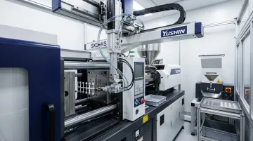
For lights-out micro molding operations, the SXC family integrates with downstream conveyors, inline vision inspection, degating stations, and Yushin's PA Series compact palletizing robots — enabling a complete unattended production cell from mold open to palletized output.
The infrastructure demands are consistent across the industry. Arburg, for example, documents MULTILIFT H 3+1 deployments with cavity-separated set-down, sprue removal, and laminar-flow clean-room modules with ionization to prevent electrostatic charging of micro components. The takeaway: a production-ready micro molding cell requires purpose-built automation at every stage — extraction, handling, inspection, and palletizing.
Frequently Asked Questions
What is micro injection molding used for?
Micro injection molding produces sub-gram, micron-tolerance components for medical devices, electronics, optics, and automotive applications. It's the preferred method when dimensional accuracy and high-volume repeatability are both required.
How small can parts be in micro injection molding?
Parts typically weigh under one gram, with some documented examples at 0.004 g. Features like holes and walls can be measured in fractions of a millimeter, and dimensional tolerances can reach ±0.0005 inches on molded parts.
What materials are compatible with micro injection molding?
Common materials include LCP, PEEK, POM/Acetal, polycarbonate, and PMMA. High-performance polymers with predictable flow behavior and specific functional properties — biocompatibility, optical clarity, thermal resistance — are preferred over general-purpose resins.
How does micro injection molding differ from standard injection molding?
The differences extend beyond part size to machine architecture, tooling precision, gate geometry, injection speed, material selection, and process control requirements. Standard molding assumptions about fill behavior, cooling, and metrology don't transfer to micro scale.
What are the biggest challenges in micro injection molding?
Tooling precision and maintenance, material flow control at micro scale, part ejection without damage, 100% inspection of tiny features, and post-mold handling and orientation. Post-mold handling is consistently underestimated until production scales.
Can micro injection molding support high-volume production?
Yes. With robust tooling, disciplined process controls, and purpose-built handling automation, micro molding supports production from thousands to billions of parts. Per-part costs drop substantially at scale, making it competitive for medical, electronics, and automotive programs.