Introduction
Producing a plastic part that fits correctly once is straightforward. Producing ten thousand identical parts — each within microns of the last — is an entirely different challenge.
Manufacturers making medical diagnostic devices, automotive sensors, or electronic connectors face this problem every day. Standard injection molding tolerates dimensional variation that these applications simply cannot accept. A connector that fits loosely fails. A diagnostic component that varies in wall thickness produces inconsistent results. The margin for error is effectively zero.
Precision plastic injection molding exists to close that gap. This article covers:
- What separates precision molding from conventional injection molding
- How each stage of the injection cycle contributes to — or undermines — dimensional accuracy
- The science of shrinkage and process control
- Why mold engineering, material selection, and automated part handling must work together to produce repeatable parts
Key Takeaways
- Precision injection molding holds tolerances of ±0.002 in. (tight) to ±0.001 in. (very tight) — far beyond standard molding specs
- Every stage of the five-stage molding cycle (clamping through ejection) must be controlled; variation in any one stage compounds into dimensional error
- Shrinkage is the primary accuracy variable, driven by thermal contraction, crystallization, and orientation effects in the polymer
- Mold engineering, polymer selection, and automated part removal function as one integrated system — optimizing each in isolation misses the full picture
What Is Precision Plastic Injection Molding?
Precision injection molding is a specialized manufacturing process that produces plastic components with extremely tight dimensional tolerances. While standard injection molding accepts wider part-to-part variation suitable for commodity applications, precision molding is designed for parts where dimensional consistency is a functional requirement, not a preference.
Defining "Precision" in Practice
Tolerance standards are source-specific and vary by feature size, material, and geometry. ISO 20457:2018 provides the formal framework for plastic molded part tolerances. In industry trade practice, SyBridge defines tight tolerance molding as ±0.002 in. and very tight tolerance as ±0.001 in., with mold tool machining at suppliers like Protolabs held to ±0.003 in. (0.076 mm). At the extreme end, micro molding — a subset of precision molding — can produce features under 1 µm and wall thicknesses as thin as 25 µm for medical and electronics applications.
Two performance indexes determine whether a precision molded part is in spec:
- Dimensional repeatability — part dimensions must fall within specification across the entire production run, not just at setup
- Weight (mass) consistency — shot-to-shot variation in part weight indicates process instability and predicts dimensional drift
What Makes It Different from Standard Molding
Precision molding is not simply a matter of running a better machine. It requires integrating four elements simultaneously:
- Higher injection pressures and tighter process windows
- Advanced tooling machined to tighter cavity dimensions than standard molds
- Continuous real-time monitoring of pressure, temperature, and fill position
- Stricter quality systems applied to every cycle, not just periodic sampling
Real-world products that require this approach include digital camera components, medical diagnostic devices, optical light guide plates, automotive sensors, computer connectors, and microfluidic chips. Beyond tight tolerances, these parts also demand high internal quality: consistent molecular structure, low residual stress, and repeatable surface finish.
The Injection Molding Cycle: How Precision Parts Are Made
Every injection molded part passes through five sequential stages. In standard molding, some variation at each stage is acceptable. In precision molding, any deviation compounds — an inconsistent fill becomes a packing problem, which becomes a dimensional error.
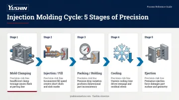
The Five Stages
Mold clamping: The two mold halves close and lock under tonnage sufficient to resist injection pressure. Inconsistent clamp force can allow flash and affect cavity geometry.
Injection/fill: Plastic pellets melt in a heated barrel, and a reciprocating screw forces a precise shot volume through the nozzle into the cavity. Shot volume consistency is the foundation of part-to-part repeatability.
Packing/holding: After the cavity is filled, holding pressure compensates for material shrinkage as cooling begins. The gate must fully solidify before pressure releases; premature release causes sink marks and dimensional shortfall.
Cooling: Temperature-controlled fluid circulates through mold channels, extracting heat at a controlled rate. Uneven or insufficient cooling causes warping and internal stress.
Ejection: Ejector pins push the part from the mold. Pin placement and ejection force must be precisely managed to avoid distorting a part that is still dimensionally vulnerable.
Scientific Molding: The Precision Approach
Traditional injection molding treats fill and pack as a continuous, pressure-driven event. Scientific (decoupled) molding separates them deliberately.
In the fill stage, velocity controls the process. According to Plastics Technology's DOE guidance, the cavity fills to roughly 98% of volume at first stage. At a defined transfer point, the machine switches from velocity to pressure control, compensating for shrinkage without overpacking.
This separation matters because fill time must stay constant to produce identical parts. Any shift in fill time requires resetting the transfer position — otherwise packing conditions change, and part dimensions change with them.
Three process checks keep this in control:
- Transfer point position: Set so the cavity reaches ~98% fill before switchover
- Fill time consistency: Deviations signal a change in material viscosity or barrel temperature
- Gate-freeze verification: Holding pressure duration is confirmed correct when shot-to-shot weight gain falls below 0.5%
The Science of Precision: Tolerances, Shrinkage, and Process Control
Achieving a tight tolerance requires understanding what causes dimensional variation. Three mechanisms drive shrinkage in injection molded thermoplastics, and each must be managed differently.
Thermal Shrinkage
As molten plastic cools inside the mold, it contracts. Higher mold temperatures increase total shrinkage; lower temperatures reduce it but can increase residual stress. Precision molding compensates by designing mold cavities slightly oversized — built to the expected finished dimension accounting for the material's known shrinkage rate — and by holding mold temperatures consistently within ±1–2°C of the target.
Phase Change Shrinkage
Semi-crystalline polymers — nylon, POM, PEEK — undergo volumetric reduction as molecular chains crystallize during cooling. This is in addition to thermal contraction. Covestro's thermoplastic shrinkage research confirms that crystallization effects add a separate shrinkage component not present in amorphous materials like polycarbonate.
Managing phase change shrinkage requires:
- Controlled cooling rates to limit crystallization speed
- Adequate holding pressures to keep material compressed during crystallization
- Careful material selection matched to the application's tolerance demands
Higher crystallinity can improve dimensional stability long-term, but uncontrolled crystallization during processing increases shrinkage variability.
Orientation Shrinkage
During injection, molecular chains stretch in the direction of flow. Upon cooling, they attempt to recoil — causing differential shrinkage between the flow direction and the transverse direction. Fiber-filled materials amplify this effect: glass fibers align with flow, creating anisotropic shrinkage where flow-direction shrinkage is dramatically lower than cross-flow shrinkage.
Gate location, injection speed, and wall thickness all influence orientation. Mold flow simulation tools like Autodesk Moldflow predict these effects before steel is cut, so engineers can optimize gate placement and minimize orientation-driven dimensional variation.
Real-Time Process Monitoring
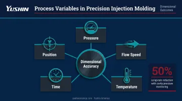
Simulation handles the design phase — but in-production control is where dimensional consistency is won or lost. Five process variables govern dimensional outcomes in injection molding:
- Pressure — fill and pack pressure profiles
- Flow speed — injection velocity through each stage
- Temperature — melt and mold surface temperatures
- Time — pack, hold, and cooling durations
- Position — screw transfer and cushion positions
Controlling all five simultaneously, cycle after cycle, is what separates precision molding from standard production.
Modern precision cells use cavity pressure sensors to monitor fill behavior in real time. Kistler documented a 50% scrap-rate reduction after introducing cavity pressure monitoring in a high-end shaver application — one of the clearest quantified cases linking real-time process monitoring to quality outcomes. Pressure-volume-temperature relationships detected by in-mold sensors allow automatic detection of process drift before it produces out-of-tolerance parts.
Mold Engineering and Material Selection for Precision
Precision Mold Design
The mold is the physical definition of the part. For precision molding, mold construction requirements are substantially more demanding than standard tooling:
- Cavity machining tolerance: Industry suppliers typically machine injection molds to ±0.005 in.; precision applications require tighter, with supplier benchmarks at ±0.003 in. (0.076 mm) or less
- Tool steel selection: High-hardness grades resist wear and deformation under the elevated injection pressures precision molding requires
- Wall thickness and rigidity: Thin mold components flex under pressure, causing dimensional drift. Precision molds use adequate wall sections to maintain cavity geometry under load.
- Runner system design: Balanced runner layouts ensure all cavities fill simultaneously at equal pressure, preventing cavity-to-cavity dimensional variation
Hot runner systems with valve gates reduce cycle-to-cycle melt temperature variation compared to cold runners and eliminate the runner waste that cold-runner tools produce.
Mold-Masters product data shows fill balance variance within 1.7% for small medical parts in hot runner applications. For multi-cavity precision tools, that level of cavity balance directly determines part-to-part dimensional consistency.
Material Selection
Not every polymer can hold tight tolerances. Precision molding materials share specific characteristics:
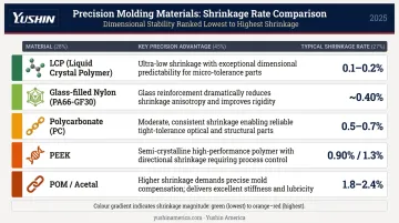
| Material | Key Precision Advantage | Typical Shrinkage |
|---|---|---|
| LCP (e.g., Vectra) | Ultra-low shrinkage, excellent dimensional stability | 0.1–0.2% (flow direction) |
| Glass-filled nylon (PA66-GF30) | High stiffness, low flow-direction shrinkage, heat resistance | ~0.40% (parallel to flow) |
| Polycarbonate (e.g., Lexan 141R) | Amorphous — predictable, isotropic shrinkage | 0.5–0.7% |
| PEEK (e.g., Victrex 450G) | High-performance, controlled directional shrinkage | 0.90% (flow) / 1.3% (cross-flow) |
| POM/acetal | Excellent stiffness, creep resistance; requires careful cooling | 1.8–2.4% |
Material selection is not interchangeable. An amorphous polymer like polycarbonate shrinks predictably and isotropically; a semi-crystalline polymer like POM shrinks more and anisotropically. For a precision connector housing, choosing the wrong polymer means the mold cavity dimensions will produce the wrong finished part — no matter how well the process is controlled. Material choice and mold geometry are interdependent decisions, not sequential ones.
Automation's Role in Precision Molding and Key Industry Applications
Why Automation Is a Precision Requirement
Manual part removal introduces variability that precision molding cannot absorb. The problem is not primarily speed — it is consistency.
After ejection, a part continues cooling and stress-relaxing. If it sits in the mold or on the ejector pins longer than designed, or if it is handled differently from cycle to cycle, dimensional variation results. For thin-walled or temperature-sensitive components, this window is especially narrow.
Automated take-out robots solve this by extracting every part at precisely the same moment in the cycle, with the same motion profile, every shot. Yushin America's take-out robot lineup is built around this consistency requirement — with specific tiers matched to application demands:
- SXC-HSY (micromolding cells) — sub-second part extraction for mold-open windows measured in fractions of a second
- RC-SE (medical and precision validation environments) — stiffer frame, premium servos, and finer motion-control resolution for cells where standard robot tiers have reached a precision ceiling
- SX-41 (cleanroom medical molding) — ISO Class 6 (ISO 14644-1) certified side-entry robot with FDA-grade lubricants and sealed bearings for cells where particulate control is as critical as extraction timing
Consistent extraction also makes lights-out production viable at scale. PlasticsToday, citing IFR data, reports that plastic molders added 1,646 robots globally in 2023, with global robot density reaching 162 robots per 10,000 employees — reflecting sustained investment in automated cells across the industry.
Industries That Depend on Precision Molding
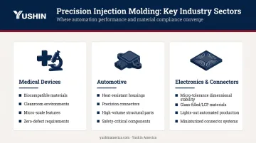
Three sectors drive the majority of precision injection molding demand:
- Medical devices and diagnostics — biocompatible materials, cleanroom environments, micro-scale features; zero-defect requirements make process monitoring and automated part handling non-negotiable
- Automotive — heat-resistant sensor housings, precision-fit connectors, structural components where assembly tolerances are tight across high production volumes
- Electronics and connectors — dimensional stability at micro-tolerances, often with glass-filled or LCP materials; high cavitation tools in automated cells for lights-out production
Each sector also benefits from integrated precision cells combining validated molding machines, real-time cavity monitoring, and robotic part handling — the combination that makes consistent quality at production volumes achievable.
Frequently Asked Questions
What is precision plastic injection molding?
Precision injection molding is a specialized process that produces plastic parts with extremely tight dimensional tolerances — defined in trade practice as ±0.002 in. for tight tolerance and ±0.001 in. for very tight tolerance — used when standard molding cannot achieve the dimensional repeatability or internal quality required for medical, electronics, or automotive applications.
How much do plastic injection molds cost?
Mold cost depends on size, complexity, number of cavities, steel grade, and required tolerances. Precision molds for tight-tolerance or high-volume applications require higher-grade tooling steel and finer machining, which raises upfront cost. That investment pays back through lower per-part costs and longer mold service life across high-volume runs.
What is the strongest plastic for injection molding?
"Strongest" depends on the property that matters: tensile strength, impact resistance, heat resistance, or creep resistance. PEEK leads on heat and chemical resistance; glass-filled nylon (PA66-GF30) reaches heat deflection up to 245°C; polycarbonate delivers impact resistance with dimensional predictability. Match the resin to the failure mode you're designing against.
What is the difference between precision and standard injection molding?
Standard molding accepts wider dimensional variation suited to commodity parts. Precision molding employs tighter mold machining tolerances, scientific (decoupled) process control, real-time cavity monitoring, and stricter quality systems to consistently produce parts within specifications that standard molding processes cannot reliably hold.
What factors affect dimensional accuracy in injection molding?
Three categories drive dimensional accuracy:
- Mold precision — cavity dimensions, machining tolerances, and tooling rigidity
- Material shrinkage — thermal contraction, crystallization in semi-crystalline polymers, and orientation effects
- Process parameters — injection pressure, melt and mold temperature, fill speed, cooling time, and V/P transfer position