Introduction
Manufacturers producing thin-wall packaging, electronics components, and consumer goods face a familiar problem: customer demand keeps growing, tolerances keep tightening, and cycle times keep shrinking. Traditional injection molding processes weren't built for this pressure.
High-speed injection molding is how leading plants are responding. Pushing injection velocities beyond 300 mm/sec — and rebuilding every element of the molding cell around that speed — lets processors cut cycle times sharply without giving up part quality.
This article breaks down injection speed fundamentals, the techniques and machine requirements behind high-speed operation, and how automation fits into a complete high-speed production cell — written for process engineers, plant managers, and operations leaders evaluating or upgrading these processes.
Key Takeaways:
- High-speed machines exceed 300 mm/sec; ultra-high-speed machines reach 600–1,500 mm/sec depending on OEM
- Thin-wall parts with L/T ratios above 150 require ultra-fast injection to fill before freeze-off
- Multi-stage speed profiling controls defects when a single fill velocity can't cover the full shot
- Accumulator-equipped hydraulic and servo-electric drives supply the instantaneous flow needed for high-speed fill
- Automation is not optional at sub-6-second cycle times — manual part removal becomes the throughput ceiling
What Is High-Speed Injection Molding?
High-speed injection molding is defined by two things: how fast the melt enters the cavity and how quickly the full cycle completes. Both matter — and they're not always aligned.
Defining the Speed Thresholds
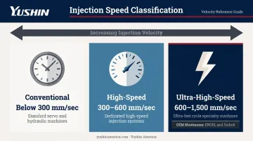
Injection speed tiers are generally understood across the industry as follows:
- Conventional: below 300 mm/sec
- High-speed: 300–600 mm/sec (varies by OEM and application)
- Ultra-high-speed: above 600 mm/sec — OEMs like ENGEL and Sodick publish maximums of 1,200–1,500 mm/sec on their fastest thin-wall platforms
Injection velocity and overall cycle time are related but distinct. A machine can hit peak injection speed and still run long cycles if plasticization, cooling, or part removal isn't optimized.
Why Thin-Wall Parts Demand It
High-speed molding is the standard approach for thin-wall products. An academic definition widely cited in injection molding literature classifies thin-wall parts as those with an L/T ratio greater than 150 — where L is flow distance from the main runner to the farthest point, and T is wall thickness.
At conventional fill speeds, the melt front cools and solidifies before the cavity is full. The result is short shots, weld lines, and incomplete fill. Ultra-fast injection keeps the melt moving fast enough to complete fill before freeze-off — which is physically necessary, not just operationally preferable.
The Shear-Thinning Principle
The physics that make high-speed molding viable: polymer melts are non-Newtonian fluids. As shear rate increases, apparent viscosity drops. Research on PS melt under ultra-high injection rates has documented shear strain rates reaching 10⁵ s⁻¹, with viscosity following power-law behavior at these conditions.
In practical terms: faster injection creates lower melt viscosity, which improves flow and reduces required injection pressure. High-speed machines are specifically engineered to exploit this behavior.
Core Techniques in High-Speed Injection Molding
Multi-Stage Injection Speed Control
Rather than injecting at a single velocity throughout fill, high-speed molding often divides the screw stroke into multiple speed segments — machines commonly offer 3, 4, or 5 injection speed settings — each calibrated to the mold geometry at that point.
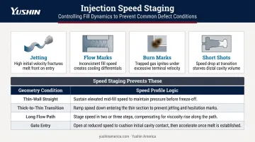
The underlying principle: melt front surface velocity should stay as constant as possible across geometry changes. When velocity fluctuates uncontrolled, defects follow:
- Jetting — from excessive gate speed
- Flow marks — from inconsistent melt front progression
- Burn marks — from trapped gas at end-of-fill
- Short shots — from premature freeze-off in thin sections
Speed staging decisions are driven by geometry:
| Geometry Condition | Speed Profile Logic |
|---|---|
| Thin-wall straight sections | Sustain high speed throughout |
| Thick-to-thin transitions | Slow → fast → slow curve |
| Long flow paths | Fast fill to prevent melt front cooling |
| Gate entry | Controlled slowdown to prevent jetting |
One important caution from process engineering practice: roughly 80% of processes use only one fill velocity, and if a single velocity works, it's easier to maintain process consistency than managing multiple stages. Speed profiling is a targeted defect-control tool, not a universal starting point.
Injection Pressure Optimization
At a given fill speed, higher injection pressure improves melt flow capability and cavity fill completeness — but excessive pressure risks flash, mold damage, and process instability.
Two pressure concepts matter here:
- Injection pressure — the force applied to the melt via the screw
- System/pump pressure — the hydraulic circuit pressure supplying that force
In high-speed molding, these don't respond identically. Changes to one don't instantly translate to the other. Process engineers who conflate them will struggle to troubleshoot fill inconsistencies.
For ultra-high-speed fill, nitrogen-charged hydraulic accumulators store pressurized fluid between shots and discharge it rapidly during injection. This delivers the large instantaneous flow volume needed without requiring a disproportionately large pump or motor.
Process Consistency and Fill Time Linearity
Maximum injection speed is rarely the correct setpoint. When a machine spends the entire fill stage still accelerating, shot-to-shot fill time varies and process control degrades. The real benchmark is whether the machine can consistently hit the target fill time — not how fast it can theoretically run.
Process engineers verify fill time linearity by:
- Monitoring screw velocity profiles across multiple consecutive shots
- Confirming peak fill speed is reached well before end of stroke
- Using cavity pressure data to check repeatable fill behavior shot-to-shot
When fill time varies even slightly between shots, dimensional variation and cosmetic defects follow.
Machine Requirements for High-Speed Operations
Drive Systems and Accumulators
Standard hydraulic pumps can't deliver the instantaneous flow volume that ultra-high-speed injection demands. The solution: nitrogen-charged hydraulic accumulators that store pressurized fluid between shots and release it in a rapid burst during injection.
This architecture keeps motor size manageable while enabling injection velocities that would otherwise require impractically large pumps.
All-electric high-speed machines use servo motors for clamping, ejection, and plasticization, offering faster response and greater precision. Servo-hydraulic hybrids remain common for high-tonnage applications. Haitian's fast-cycle machine documentation cites 20–80% electricity savings versus conventional hydraulic equipment, depending on application.
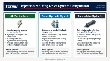
Drive system selection affects more than energy costs. Key tradeoffs include:
- All-electric servo: Fastest response, highest precision, best energy efficiency — suited to thin-wall and high-cavitation packaging
- Servo-hydraulic hybrid: Balances speed with the clamping force needed for high-tonnage tooling
- Accumulator-hydraulic: Cost-effective for ultra-high-speed injection where all-electric tonnage is insufficient
Control System Demands
High-speed molding places extreme demands on the control architecture:
- Servo or proportional valves with response times of 0.01 seconds or faster
- Servo control update rates at 0.001 seconds or better
- Compensation algorithms for nonlinear valve behavior under load variation
Equally important is mold clamping rigidity. At high injection speeds with low-viscosity melts, even minor platen flex or tie-bar misalignment creates flash. High-speed machines require superior tie-bar parallelism, stiffer platens, and clamping mechanisms capable of maintaining consistent clamp force throughout fast fill events.
Plasticization Capacity
In ultra-high-speed molding, the injection stroke itself is extremely short. The bottleneck often shifts to plasticization time — how quickly the screw can prepare a full, uniform shot for the next cycle.
Optimizing screw design, screw speed, backpressure, and barrel temperature together ensures plasticization completes before the next cycle begins — making it the primary constraint in most ultra-high-speed cells.
High-Speed vs. Standard Injection Molding
Operational Differences
Standard machines work sequentially: clamp → inject → cool → plasticize → open → eject. High-speed machines overlap these actions through three-axis linkage — mold opening, ejection, and material storage occur simultaneously rather than in sequence.
The result: measurably shorter dry cycle times. ENGEL's motion control optimization reduced dry cycle time by approximately 10% in documented testing (3.15 seconds to 3.00 seconds), while JSW reports a 16% dry cycle reduction on its high-cycle toggle mechanism versus conventional machines.
Those gains compound fast at high cavitation counts — which is why the energy profile of the machine driving the cycle matters just as much as the cycle time itself.
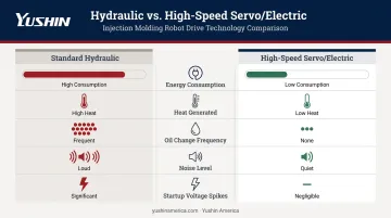
Environmental and Energy Profile
| Factor | Standard Hydraulic | High-Speed Servo/Electric |
|---|---|---|
| Energy consumption | Higher | Substantially lower |
| Heat generated | More | Less |
| Oil change frequency | Higher | Lower |
| Noise level | Higher | Lower |
| Startup voltage spikes | Common | Minimized |
Investment Consideration
The servo/electric advantage on energy and heat also reduces operating costs over time — but high-speed machines still carry a higher upfront price tag. That premium pays off when:
- Production volume is high enough to amortize the premium
- Applications involve thin-wall or high-cavitation tooling
- Faster output drives per-part cost low enough to recover the difference
For low-volume or thick-wall applications, the math usually favors standard machines — lower upfront cost, simpler maintenance, and no penalty for slower cycle times.
Applications and Industries
High-speed injection molding serves three distinct application categories:
Thin-wall consumer goods with loose dimensional tolerances — disposable cups, food containers, clamshell packaging. Speed matters most; dimensional precision is secondary.
Precision industrial and electrical components — connectors, gears, filters, oil seals. These require thin walls and tighter dimensional control.
High-precision electronic and optical products — IC trays, optical fiber connectors, camera components, non-contact IC cards. Mechanical, optical, and electrical properties must all meet tight specifications simultaneously.
The Insight Partners projects the high-speed injection molding machine market to reach USD $8.99 billion by 2034 at a 6.51% CAGR, driven by miniaturization demands across 3C electronics, automotive lightweighting, and medical devices.
Material Compatibility
The best-performing resins for high-speed molding share two characteristics: high melt flow index and pronounced shear-thinning behavior. Not every resin qualifies.
- PP — the dominant resin for thin-wall food packaging; high-flow grades with MFR of 50–75 g/10 min are standard for sub-6-second cycles
- PE — HDPE and LDPE grades in the 20–40 g/10 min MFR range are common for bottles, caps, and flexible packaging where cycle speed outweighs stiffness requirements
- Engineering resins — high-flow PA, POM, and LCP grades engineered for thin-wall connectors and precision electrical components where MFI above 30 g/10 min is typical
Material selection doesn't end at resin type. High-speed fill amplifies sensitivity to inconsistencies in the feedstock itself — moisture-sensitive resins need thorough drying before processing, because elevated shear rates accelerate moisture-induced degradation and can compromise part integrity.
Automation's Role in High-Speed Injection Molding
The Cycle Time Ceiling Problem
As machine cycle times shrink to the 3–6 second range in high-speed thin-wall applications, manual part removal becomes the hard constraint on productivity. A human operator physically cannot remove parts consistently within a 3-second window. Inconsistent removal timing introduces variation in part cooling history, which shows up as dimensional and cosmetic defects.
Robotic take-out systems eliminate this ceiling. A robot synchronized with the molding machine maintains consistent extraction timing shot-to-shot, preventing parts from over-cooling in the mold and sustaining cycle time discipline across an entire shift.
The robot must be in position and ready the moment the mold opens, extracting parts quickly to minimize mold-open time — one of the most controllable variables in overall cycle time reduction.
Matching Robot Capability to Cell Speed
Controlling mold-open time starts with matching the robot to the cell's cycle speed. Yushin's take-out robot lineup is structured around cycle time tiers for exactly this reason:
- HST Series — engineered for sub-10-second cycles; demonstrated 0.5-second take-out on an 8-cavity thin-wall medical mold within a 3-second overall cycle at NPE 2018
- HSA Series — tuned for sub-5-second cycles in IML packaging and ultra-short-cycle caps and closures programs
- TSXA Super-High-Speed Side-Entry — engineered for sub-3-second IML cycles; side-entry geometry enables simultaneous label placement and part extraction on a single mold-open pass
For high-cavitation programs, Yushin's double-wing EOAT configurations allow a single robot entry to simultaneously place labels and extract finished parts — maximizing cavities per minute without extending mold-open time.
Sustaining Throughput Through the Full Cell
The molding machine and take-out robot are only two elements of a complete high-speed production cell. Throughput gains disappear if downstream handling can't keep pace.
A well-integrated cell typically includes:
- HST, HSA, or TSXA take-out robot (matched to cycle speed) for consistent, repeatable part extraction
- Conveyor handoff moving parts downstream without creating bottlenecks
- PA-40 Compact Palletizing Robot, rated at 420 boxes per hour, keeping pack-out pace with upstream output
- INTU LINE IoT monitoring for real-time cycle time tracking, uptime ratios, and remote fault notification — the infrastructure for lights-out production
At sub-5-second cycle times, the molding machine's speed only translates to real output if every downstream element keeps up. Automation isn't the support system — it's the production system.
Frequently Asked Questions
What is injection speed in high-speed injection molding?
Injection speed is the forward velocity of the screw during the fill stage, measured in mm/sec. High-speed machines operate in the 300–600+ mm/sec range; ultra-high-speed machines exceed 600 mm/sec, with some OEM platforms reaching 1,200–1,500 mm/sec. Note that screw velocity and melt front velocity inside the cavity differ based on cavity geometry.
What is rapid injection molding?
Rapid injection molding refers to processes prioritizing very short cycle times and fast cavity fill — often used interchangeably with high-speed injection molding in a production context. The term also applies to rapid tooling or prototype molding services that compress lead times from weeks to days. In production discussions, cycle-time reduction is the more common meaning.
What is the 2K (two-shot) injection molding process?
Two-shot molding injects two different materials or colors sequentially into the same mold to produce a single composite part. It's distinct from high-speed molding — which focuses on cycle velocity, not material combination — though 2K processes can run on high-speed platforms for precision multi-material components.
What materials are best suited for high-speed injection molding?
PP and PE with high melt flow indices are the primary choices for thin-wall packaging applications. Certain engineering resins with optimized MFI are used for precision components. Moisture-sensitive resins require thorough drying before processing, since high shear rates during fast fill amplify degradation from residual moisture.
What common defects occur in high-speed injection molding and how are they prevented?
The most common defects are flash (excessive speed or pressure), jetting (incorrect gate-speed transitions), burn marks (trapped end-of-fill gas), and short shots (premature freeze-off). Multi-stage speed profiling, proper mold venting, and accumulator tuning prevent most of these — with mold design as the foundation.
How does high-speed injection molding affect mold design and tooling?
High-speed molds demand enhanced venting, rigid parallel plates to resist flash under rapid fill pressure, and gate/runner geometry sized for high flow rates. These requirements push tooling costs above standard-speed applications, and gate placement with cooling channel design become especially critical to final part quality.