Standard injection molding works well for most applications. But when your part requires near-zero birefringence, tight dimensional tolerances, or warpage control that standard IM cannot deliver, ICM becomes a serious option — not an academic one. This article covers exactly how ICM works, what distinguishes it from standard and compression molding, which process variables matter most, and when ICM is not worth the added complexity.
Key Takeaways
- ICM fills a partially open mold then compresses it, cutting injection pressure and residual stress compared to standard injection molding
- Preferred for optical lenses, automotive glazing, and precision thin-walled parts where low internal stress is a hard requirement
- Five variables govern ICM outcomes: compression gap, shot volume, compression speed/force, mold temperature uniformity, and gate design
- ICM requires machines specifically configured for controlled compression — standard toggle-clamp presses are generally not suitable
- ICM is not universally better; it adds process complexity that is only justified for specific materials, geometries, and quality requirements
What Is Injection Compression Molding?
ICM is a molding process in which plastic melt is injected into a mold cavity that is not yet fully closed. Once the programmed injection volume is delivered, the mold closes under controlled compression force, distributing the melt uniformly across the cavity and reducing flow-induced stress as it achieves final part geometry.
The process is designed to produce uniform melt distribution at lower injection pressures — which translates directly to reduced molecular orientation, lower residual stress, tighter dimensional tolerances, and better optical clarity in the finished part.
How ICM Differs From the Alternatives
Understanding ICM requires distinguishing it from two related but distinct processes:
| Process | How Cavity Is Filled | Pressure Mechanism |
|---|---|---|
| Standard Injection Molding | Fully closed rigid cavity | High injection/packing pressure through gate |
| Compression Molding | Pre-formed charge placed in open mold | Compression force only; no injected flow |
| Injection Compression Molding | Partially open cavity, then compressed | Injection delivers melt; compression distributes it |
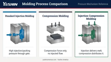
ICM intentionally combines the controlled material delivery of injection molding with the low-pressure distribution of compression molding. As noted in ScienceDirect's overview of injection-compression molding, compression supplies a major part of the filling and packing pressure — making ICM a physically distinct process, not simply an additional packing stage bolted onto standard injection molding.
Why Injection Molding Plants Use ICM
ICM adoption is application-driven. Plants choose it when standard injection molding produces unacceptable results for a specific part — not as a general upgrade, but as the only process that works.
Where Standard IM Falls Short
In a fully closed cavity at high injection pressure, melt experiences significant shear at the gate and along flow fronts. The result:
- Molecular orientation frozen into the part at gate areas and flow extremities
- Residual stress that degrades optical performance and increases post-mold warpage risk
- Birefringence in transparent parts, making them functionally unacceptable for optical applications
- Sink marks and non-uniform density in thin-wall regions where packing pressure drops off
For a smartphone lens or an automotive headlamp cover, these are not cosmetic concerns. They are functional failures.
Established ICM Applications
ENGEL's coinmelt injection-compression documentation and simulation platforms such as Moldex3D's ICM module consistently identify the same core application categories:
- Precision optical lenses — camera lenses, eyeglass lenses, Fresnel lenses, where birefringence must be minimized
- Automotive polycarbonate glazing — large transparent PC panels where both optical clarity and warpage control are required; ICM is the established process for this segment
- Thin-walled light guide panels — where compression enables uniform filling across long, thin flow paths that standard IM cannot reliably fill at acceptable stress levels
- Thin-wall packaging — where reduced injection pressure and clamping-force demand improve wall thickness uniformity
The Material Connection
ICM is particularly necessary for high-viscosity optical-grade polycarbonate (PC) and PMMA (acrylic). These materials are both difficult to fill at standard injection pressures and highly sensitive to the orientation stress that high shear produces. For PC automotive glazing or PMMA optics, ICM is not an optimization — it's the process that makes acceptable parts possible.
The same process characteristics that make ICM viable for these materials carry a capital equipment consequence: clamping force requirements drop relative to standard injection molding for equivalent part size. For plants evaluating machine tonnage on a new program, that reduction can shift which press class is feasible.
How Injection Compression Molding Works
ICM follows a specific sequence. Every phase matters, and the variables within each phase must be pre-programmed and repeatable.
Step 1: Partial Mold Closure and Injection
The mold starts at a controlled gap — the compression gap — rather than in the fully locked position. The melt is injected into this larger-than-final cavity volume.
Injecting into the open cavity reduces shear rate and injection pressure compared to filling a fully closed mold. This is the primary mechanism by which ICM reduces flow-induced molecular orientation. Less shear during fill means less orientation frozen into the part.
Two timing variants exist for how injection and compression relate:
- Sequential ICM — injection completes first, then compression begins. Better suited for parts where the melt must distribute in a controlled pattern before compression force is applied
- Simultaneous ICM — compression begins while injection is still occurring. Useful for thin-wall or large-area parts where maintaining a moving flow front is necessary to prevent premature freeze-off
Autodesk Moldflow and Moldex3D both support configuration of either variant.
Step 2: Compression Phase
Once the programmed injection volume is delivered, the clamping unit drives the mold to its fully closed position under a controlled compression force and speed profile.
Rather than relying on injection pressure through the gate to pack the part, the closing mold surface pushes melt uniformly across the entire cavity. This produces:
- More uniform density throughout the part cross-section
- Reduced sink marks
- Lower residual stress compared to gate-driven packing
- Better surface replication for optical parts
The compression speed and force are programmable on modern ICM-capable machines — this is not a fixed mechanical event.
Step 3: Hold, Cooling, and Part Removal
The mold remains under compression force while the part solidifies. This maintains dimensional control and compensates for volumetric shrinkage without relying solely on packing pressure through the gate — a key advantage for parts where gate-area stress must be minimized.
Once the part reaches ejection temperature, the mold opens and the part is removed. In production environments handling optically sensitive or thin-walled ICM parts, automated take-out is essential for protecting part quality and maintaining cycle time consistency.
Several Yushin America robots are well-matched to ICM part removal requirements:
- RC-SE — optical-grade and Class-A surface parts on 100–800 ton presses
- SX-41 — clean-room side-entry, ISO Class 7/8 compatible, FDA-grade vacuum EOAT, purpose-built for optical molding cells
- FRA Series — larger automotive glazing panels on 400–1,500 ton presses
All three use servo-driven motion profiles, programmable deceleration, and vacuum-first end-of-arm tooling. This minimizes mechanical contact and shock during extraction, preserving the stress-free part quality that the ICM process produces.
For micro-optical components, the SXC series (SXC / SXC-HS / SXC-HSY) provides micro-vacuum EOAT and vision-guided pick capabilities suited to small-format precision optics. Contact Yushin America directly for ICM-specific application engineering consultation.
Key Factors That Affect ICM Outcomes
ICM has a narrower process window than standard injection molding. Five variables are particularly critical:
Compression gap at injection — Controls how much pressure-reduction benefit you get from ICM. Too large a gap risks asymmetric filling or overflow before compression begins; too small reduces the shear-rate benefit. The right gap requires process development specific to each part geometry.
Melt shot volume accuracy — Because compression distributes the melt rather than additional injection pressure, shot-to-shot volume consistency is more critical than in standard IM. Excess material causes flash when the mold closes; insufficient material causes incomplete fill that compression cannot correct.
Compression speed and force profile — The rate and force of mold closing directly controls shear stress on the cooling melt front. Too fast risks flow marks or distortion; too slow allows premature solidification before full fill is achieved. Both parameters are programmable on ICM-capable machines and must be optimized per application.
Mold temperature uniformity — ICM distributes melt simultaneously across the entire cavity during compression, making it particularly sensitive to non-uniform mold temperature. Hot spots and cold spots produce differential shrinkage and warpage — the same problem ICM is meant to solve. For optical-grade parts, uneven mold temperature translates directly to warpage and rejected parts.
Gate design and location — In standard IM, gate position primarily governs filling pattern. In ICM, gate location also determines how the melt spreads across the cavity before compression begins. Fan gates and edge gates work best for ICM optical applications — they support broader, more uniform pre-compression melt distribution than pin gates or submarine gates.
Common Misconceptions and When ICM Is Not the Right Choice
Two Misconceptions Worth Addressing Directly
The first misconception is that ICM is simply injection molding with compression added at the end. It isn't. The compression gap during injection fundamentally changes the melt flow physics. Injecting into an open cavity reduces shear rate from the start of fill — this alters the entire molecular orientation history of the part, not just the packing stage.
The second is that any injection molding machine can run ICM with software changes. ICM has specific hardware requirements that software cannot substitute:
- Precise parallel mold movement during the compression phase
- Programmable compression force and speed profiles
- Hydraulic, servo-hydraulic, or OEM-configured two-platen machine architecture
Standard toggle-clamp machines approach lockup with increasing mechanical advantage and generally cannot deliver the controlled compression stroke ICM requires.
When ICM Is Not the Right Process
Addressing those misconceptions also clarifies where ICM actually fits. The process adds real complexity — and that complexity is not justified for:
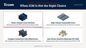
- Thick, chunky cross-sections where internal stress is not a functional concern for the application
- High-volume commodity parts where cycle time economics favor standard IM and part quality tolerances are well within what standard IM can achieve
- Complex geometries with deep undercuts, cores, or multiple slides that make a controlled compression stroke mechanically impractical
- Non-stress-sensitive materials — unfilled PP, standard ABS, and similar materials rarely exhibit the stress sensitivity that motivates ICM adoption in the first place
One reliable indicator of a misfit selection: a team defaults to ICM because a similar part elsewhere in the facility uses it. If the specific material, geometry, and quality requirements don't actually demand it, the added equipment investment and process complexity aren't worth it.
Frequently Asked Questions
What is injection compression molding?
ICM is the process of injecting plastic into a partially open mold cavity, then closing (compressing) the mold to complete filling and pack the part. It differs from standard injection molding (which fills a fully closed cavity at high pressure) and from pure compression molding (which compresses a pre-formed charge without injected flow).
What is the difference between compression and injection molding?
Standard injection molding fills a fully closed cavity at high pressure through a gate. Compression molding places a pre-formed charge in an open mold and compresses it without injected flow. ICM combines both: it injects melt into a partially open cavity, then compresses to distribute and pack the material at lower pressure than standard IM.
What materials are best suited for injection compression molding?
Optical-grade polycarbonate (PC) and PMMA benefit most from ICM due to their high viscosity and sensitivity to flow-induced stress and birefringence. Other engineering thermoplastics with tight warpage or dimensional tolerance requirements can also be processed via ICM where the application justifies it.
What types of parts are most commonly made with injection compression molding?
Precision optical lenses, automotive polycarbonate glazing panels, thin-walled light guide panels, and certain thin-wall packaging formats — applications where low residual stress, high optical clarity, or uniform wall thickness are functional requirements.
Does injection compression molding require special equipment?
Yes. ICM requires machines capable of parallel (non-tilting) mold movement during compression, along with programmable compression force and speed profiles. Standard toggle-clamp presses typically need specific OEM configuration to support ICM operation.
Is injection compression molding faster or slower than standard injection molding?
ICM cycle times are generally comparable to or slightly longer than standard IM. For precision optical or glazing parts, lower scrap rates and reduced post-mold rework typically offset that difference in total production cost.