
Injection molding is widely used to produce precision plastic components at scale, including medical equipment housings, optical parts, electronic connectors, and other small or complex molded components. The process can support repeatable geometry, multi-cavity production, complex features, and a broad range of engineering polymers when the tooling and process are appropriately designed.
When those molded parts serve demanding applications - and medical equipment components are among the most demanding - the requirements placed on the automation surrounding the injection molding machine (IMM) shift significantly. The mold still produces the part. What changes is everything that happens from the moment the mold opens until the part reaches its downstream destination.
This article focuses on that gap: what robot and end-of-arm tooling (EOAT) selection looks like when molded parts must be handled in a clean, precise, tightly controlled production environment.
Why Injection Molding Is Used for Precision Plastic Components
Injection molding is widely used for precision plastic component production because it can support repeatable geometry, complex features, thin-wall designs, and multi-cavity output. Once tooling and process conditions are established, the molding sequence can be repeated across production runs. A wide range of engineering polymers are also used in optical, electronic, medical equipment, and other precision applications.
For precision applications where geometry, surface condition, and dimensional consistency directly affect downstream function, injection molding gives manufacturers a foundation for quality that begins at the press. The automation connected to that press determines whether the quality achieved inside the mold is preserved through extraction, handling, and placement.
What Changes When Parts Demand a Clean, Controlled Production Environment

The central question for any molder handling precision components in a controlled environment is this: what does the robot and EOAT selection process look like differently here compared to a standard commodity molding cell?
The answer touches equipment design, contamination risk, extraction path, contact surfaces, repeatability, part orientation, and downstream placement - each of which is worth examining in turn.
Clean Production Environments: Equipment Design and Particle Generation
The cleanliness classification of a production environment - defined under ISO 14644-1 by maximum allowable airborne particle counts at specific sizes per cubic meter of air - sets the baseline requirement for every piece of equipment operating inside that space.
Robot selection for clean environments should consider the complete robot configuration rather than entry direction alone. Particle generation, moving components, bearing and drive design, cable routing, lubrication, robot motion, EOAT, and the location of that motion relative to the open mold can all affect suitability for a controlled environment.
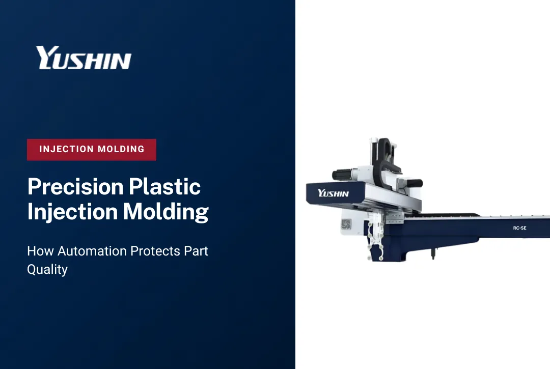
Side-entry robots such as Yushin's SXB side-entry take-out robot can be useful when the application benefits from keeping moving robot components away from the area above the open mold. However, side-entry architecture is not the only option for cleanroom automation. Yushin can also customize suitable RC/RC-SE, YD/YD2, and FRA take-out robot configurations for cleanroom operation after reviewing the molding cell and its cleanliness requirements.
Cleanroom-oriented configuration can also involve details such as sealed bearings and belt-drive systems, which Yushin frequently uses in suitable robot configurations to support controlled-environment operation. Material compatibility, lubrication, seals, EOAT materials, and other application-specific requirements should also be reviewed for the intended production environment.
Contamination Control Through Robot and EOAT Design
Robot architecture is one part of contamination-control planning, but the complete robot configuration and EOAT also matter. Bearings, drive components, seals, lubrication, cable routing, moving surfaces, and the tooling that contacts the molded part should all be considered when automation is specified for a controlled environment.
Application-specific EOAT engineered for a particular part geometry can minimize the contact area and contact force applied during extraction and transport. Tooling that is designed around the part - rather than adapted from a general-purpose design - limits unnecessary surfaces, reduces crevices that trap debris, and is easier to clean between production runs.
For high-cleanliness applications, EOAT material selection matters too. Surfaces that resist particle generation, can be wiped down or cleaned without degradation, and do not react with the molded material reduce the maintenance burden in a controlled environment.
Controlled Part Extraction: Path, Positioning, and Repeatability
Precision parts extracted from tight-tolerance tooling require the robot to enter and exit the mold space accurately, cycle after cycle. Even small variation in extraction path can produce contact between the EOAT and mold surfaces, or between the part and adjacent tooling, creating damage or dimensional error that may not be visible until downstream inspection.
Servo-driven robots with repeatable programmed motion help maintain a consistent extraction path across production cycles. This becomes particularly important in micro-molding and other precision applications where the robot and EOAT must enter a restricted mold area, extract small parts consistently, and deliver them to downstream equipment at a defined position.
For applications suited to a purpose-designed side-entry cleanroom configuration, Yushin's SX-41 is an available option for cleanroom molding and micro-molding, including medical equipment, optical parts, electronic parts, and other precision products. Its side-entry architecture keeps sliding and moving robot components away from the area above the mold, while other Yushin take-out robot families can also be customized for cleanroom operation when the application requires a different configuration.
Minimal Unnecessary Contact: EOAT Design Principles

EOAT contact force should be appropriate for the molded part and its condition at extraction. Parts that are still warm after ejection can be marked by excessive gripper pressure, while parts with sensitive surface requirements may be scratched or damaged by tooling that is not matched to the part geometry and material.
EOAT designed for precision molded components is built around the principle of minimum necessary contact. This means contact surfaces matched to part geometry to distribute load, gripper force controlled to the minimum needed for reliable retention, and vacuum or non-contact gripping methods where part geometry allows.
For parts with sensitive surfaces or challenging geometries, Yushin's application engineering team works with the molder to develop EOAT that reflects the part's specific requirements rather than starting from a catalog selection.
Repeatable EOAT Positioning and Cycle-to-Cycle Consistency
Downstream quality processes - camera inspection, assembly fixtures, tray nests - are designed to receive parts at a defined position and orientation. If the robot delivers parts with any variation in grip location or handoff position, every downstream station must accommodate that variation, or reject parts that fall outside tolerance.
Repeatability in EOAT positioning across the cycle directly supports downstream quality. It reduces false rejects at inspection, improves assembly yields, and allows tighter tolerances at each downstream step. This is why cycle-to-cycle consistency in part handling is treated as a quality parameter in precision molding cells, not just a throughput metric.
Part Orientation: Supporting Downstream Inspection and Placement

The orientation in which a part arrives at an inspection camera or assembly fixture matters as much as the part's dimensional accuracy. A correctly molded part delivered to a camera inspection station at the wrong angle may fail a vision check - not because the part is bad, but because the inspection system cannot evaluate the feature it is looking for.
EOAT designed with downstream orientation in mind, combined with robot programming that places parts consistently relative to the inspection or placement station, can reduce inspection errors caused by inconsistent presentation. For precision components, orientation requirements should therefore be considered when the EOAT, robot path, and downstream inspection process are designed.
Gentle Part Release and Surface Protection
Release is the final step in the handling sequence and one of the most consequential. Parts dropped onto conveyors, collided against each other in bulk containers, or released from excessive height can be marked, cracked, or otherwise compromised in the final moment before they leave the robot's control.
Controlled part release - placing parts into trays, nests, or fixtures at a defined position and with appropriate release force - can help protect parts after extraction. For components with cosmetic requirements, orientation requirements, or sensitivity to part-on-part contact, tray or nest placement may be preferable to bulk release depending on the production process.
Vision and Inspection Integration
Where part quality verification is required at the cell level, camera-based inspection can be integrated into the robot cell after extraction. The robot presents each part to a fixed camera position, inspection software evaluates the defined features, and parts that fail are diverted before they reach downstream packaging or assembly.
This integration works most effectively when EOAT positioning is consistent - reinforcing the connection between extraction repeatability and downstream inspection performance. Yushin's automation team works with molders to define how inspection is incorporated into the cell layout and handoff sequence when vision systems are part of the requirement.
Tray and Fixture Placement: Controlled Downstream Handling
Precision molded components are rarely well-served by bulk conveyor discharge at the end of the robot cycle. Parts that need to maintain orientation for downstream assembly, or that must not contact each other to avoid surface damage, require placement into trays, nests, or fixtures.
Yushin side-entry robots and downstream automation integrate to support controlled tray or fixture placement as part of the cell. Part count per tray, placement sequence, and tray advance can be configured to match downstream requirements - whether that means a manual inspection station, an automated assembly cell, or a packaging system.
Changeover in Controlled Environments
Tooling changeover in a controlled production environment carries considerations that do not apply in a standard cell. EOAT must be cleaned before reuse or exchanged for a clean set. Components that contact the part must be inspectable and replaceable without introducing contamination. Changeover procedures should be defined and documented to maintain environmental control through the transition.
Equipment design that simplifies EOAT exchange - tool-free connections, modular tooling architecture, and quick-change interfaces - reduces the time the environment is exposed during changeover and lowers the risk of procedure variation. When evaluating robot and EOAT systems for clean production environments, changeover design should be part of the specification conversation.
Maintenance in Controlled Environments
Scheduled maintenance in a controlled production environment requires planning that accounts for the environment. Lubrication intervals, seal inspection, and bearing replacement all generate the potential for particle introduction if not managed carefully. Maintenance procedures should define what can be done in-cell and what requires the robot to be removed from the controlled area.
EOAT cleaning between runs - wiping contact surfaces, inspecting vacuum cups for wear, and checking gripper jaws for debris accumulation - is a routine step that supports contamination control between production cycles. The maintenance practices surrounding the robot are as much a part of the contamination control plan as the robot's design.
Cell Layout and Equipment Selection
The full automation cell - robot, EOAT, inspection system, and downstream placement - should be evaluated together rather than as isolated equipment choices. Cleanroom suitability depends on the complete robot configuration, component and drive design, EOAT, mold-area layout, part travel path, and downstream handling requirements. Side-entry may be advantageous in some cells, while customized traverse configurations may be appropriate in others.
For precision and medical equipment molders reviewing their cell configuration, the right starting point is a review of the IMM, the part geometry, the EOAT requirements, the clean-environment constraints, the extraction path, the inspection requirements, and the downstream placement method - before selecting a robot configuration. Each element of that review shapes the right specification.
Yushin America's application engineering team supports that process - from initial cell review through EOAT design, integration planning, and commissioning. Contact Yushin's services team to discuss your specific IMM, part, and environment requirements.
Frequently Asked Questions
Do cleanroom injection molding applications require a side-entry robot?
No. Side-entry robots can be useful when the application benefits from keeping moving robot components away from the area above the mold, but entry direction alone does not determine cleanroom suitability. Yushin can also customize suitable RC/RC-SE, YD/YD2, and FRA take-out robot configurations for cleanroom operation. Robot design, sealed components, drive configuration, EOAT, mold layout, cleanliness requirements, and downstream handling should all be reviewed for the specific application.
How does EOAT design affect contamination control in precision molding cells?
EOAT design determines what surfaces contact the part and with how much force. Tooling engineered for a specific part geometry minimizes unnecessary contact area, reduces crevices that accumulate debris, and can be fabricated from materials suited to cleaning and maintenance in a controlled environment. General-purpose tooling adapted to a specific part introduces more contact surface and is typically harder to clean and inspect.
What role does part handling repeatability play in downstream inspection performance?
Vision inspection and assembly fixtures are built to evaluate or receive parts at a defined position and orientation. When EOAT positioning varies cycle to cycle, parts arrive at inspection with small but accumulating position differences that generate false rejects - parts that pass dimensional requirements but fail the vision check because the feature being evaluated is outside the camera's evaluation zone. Consistent extraction and handoff position directly improves true inspection yield.
When should precision molded parts be placed into trays or nests rather than discharged onto a conveyor?
Tray or nest placement may be appropriate when parts must maintain orientation for downstream assembly or inspection, when part-on-part contact could cause surface damage, or when the geometry or material requires controlled release. Whether controlled placement is necessary depends on the part, quality requirements, downstream process, and production method.
What should be included in a changeover procedure for robot cells in controlled production environments?
Changeover procedures for controlled environments should address: EOAT cleaning or exchange before the new run begins, verification that all components contacting the new part are appropriate for the material and environment, documentation of the procedure to ensure consistency between operators and shifts, and confirmation that the extraction path and downstream placement positions are validated for the new tooling configuration before production starts.
How should a molder approach robot and EOAT selection for a new precision molding cell?
Start with a review of the specific requirements before selecting equipment: the IMM and mold configuration, the part geometry and material, the cleanliness requirements of the production environment, the extraction path constraints, any inspection or verification requirements at the cell level, and the downstream handling method. These inputs together define the robot architecture, EOAT design, and cell layout that will actually meet the production requirement - rather than a general-purpose selection that is later adapted at higher cost.