
Automotive plastic injection molding is a well-documented subject. What gets less attention is what automotive production demands from the automation system around the molding machine. Large parts, cosmetic quality requirements, high-tonnage machines, insert loading, and long program durations each place specific engineering requirements on the take-out robot, end-of-arm tooling, and downstream automation. This article covers those requirements - and what to think through before a production cell is finalized.
What Automotive Injection Molding Involves
Automotive injection molding is used for exterior, interior, under-hood, structural, electrical, and other vehicle components. The exact resin, mold, machine, and quality requirements vary by part and program, but automotive molding commonly places demanding requirements on dimensional consistency, surface quality, durability, repeatable production, and downstream handling.
Volumes are high, programs run for years, and OEM and Tier-1 quality systems leave little tolerance for inconsistency. These fundamentals shape every aspect of the automation design.
What Automotive Production Demands from the Robot and Automation System

Large and Complex Parts: Sizing the Robot for the Application
Bumper fascias, instrument panel substrates, door panels, and other automotive components can create demanding reach, stroke, payload, and part-support requirements. Large automotive applications may require high-tonnage IMMs and long robot travel, but there is no single machine-size range that applies to every automotive part.
Traverse beam length, vertical stroke, kick reach, payload, and the EOAT extraction path must therefore be sized to the actual IMM, mold, part geometry, and downstream placement requirement. Robot sizing should begin with the real machine and mold dimensions rather than a generic automotive tonnage assumption.
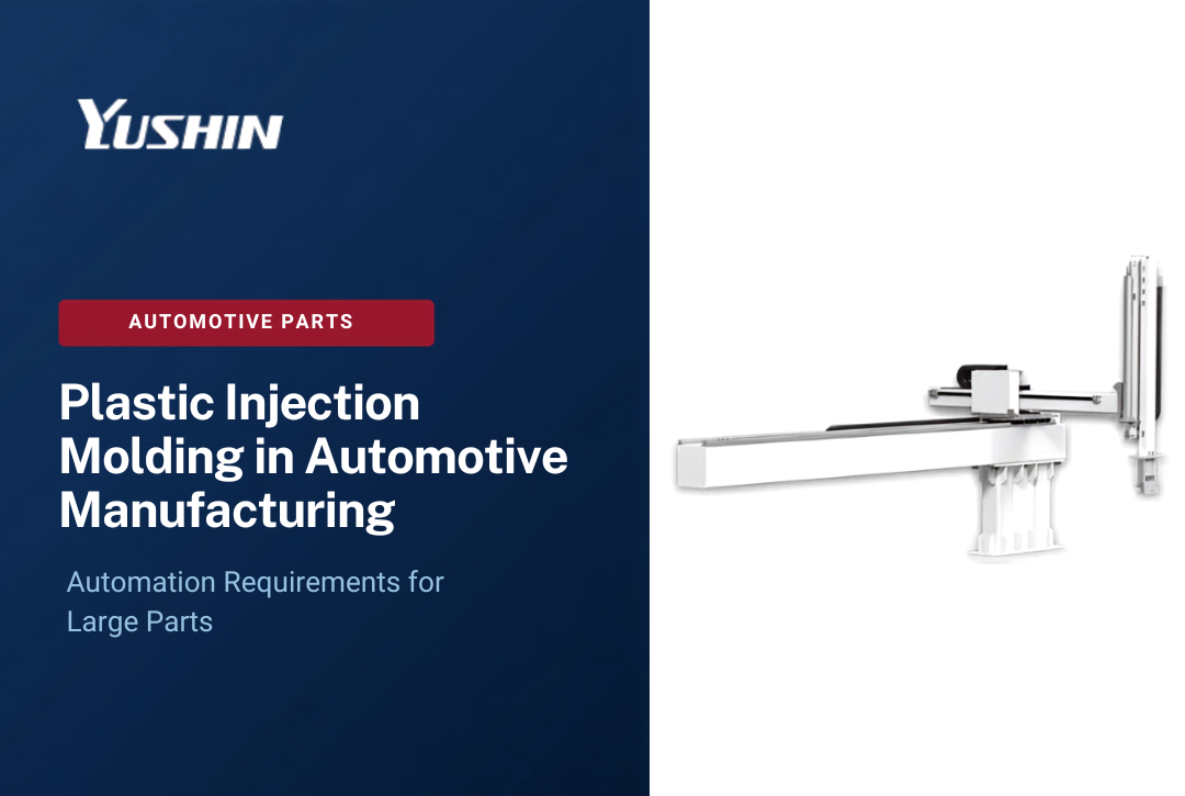
For large-format automotive take-out, the Yushin MKA-2000S large robot is designed for presses of 1,500 tons and above, handles 30-50 kg payload including EOAT, and features a two-stage telescopic vertical arm with traverse beam adjustable up to 5,000 mm and vertical strokes up to 3,000 mm. For mid-range automotive applications on 1,000-1,300-ton machines, appropriate models in the YD/YD2 large-part series cover payload requirements up to 35 kg including EOAT.
Cosmetic Part Handling: Protecting Class A Surfaces
Automotive exterior panels and visible interior trim carry strict cosmetic acceptance criteria. OEM customers inspect for surface scuffs, contact marks, tooling impressions, and any deformation that affects appearance. A part that comes through the mold perfectly can still be rejected if the extraction process contacts the surface incorrectly.
Automated extraction protects cosmetic quality by applying the same grip forces, at the same contact points, on the same extraction path, every cycle. Manual extraction varies - the grip changes, the path is inconsistent, and a tired operator at the end of a shift handles the part differently than at the start. Automation eliminates that variability.
EOAT contact point design matters as much as robot motion. Contact surfaces on cosmetic-face panels use materials and geometries chosen specifically to avoid marking. Suction cup diameter, durometer, and placement are all part of the cosmetic EOAT engineering - not afterthoughts.
Part Deformation and Flexing: Supporting Large Thin-Wall Parts
Large thin-wall automotive parts flex when unsupported. A bumper fascia supported only at two points across a 1.5-meter span will sag. If the part sags during extraction, it can contact mold steel, deform, or cool into a shape that does not meet dimensional specifications.
Multi-point EOAT distributes grip force across the part surface, maintaining the part's geometry from the moment it releases from the mold through the entire extraction and placement path. The number of contact points, their spacing, and the structure of the EOAT frame are all engineering decisions specific to each part geometry. A standard two-point gripper designed for small parts will not transfer to an automotive panel application.
Multi-Point EOAT Engineering

For automotive-scale parts, EOAT is not a commodity item purchased off a shelf. It is an engineered assembly specific to each part and each mold. Engineering considerations include:
- Grip point layout: contact locations selected to distribute load without deforming the part, avoiding thin sections, gating areas, or cosmetic surfaces
- Frame stiffness vs. weight: the EOAT structure must be rigid enough to control the part during motion, while light enough to remain within the robot's effective payload capacity when combined with the part weight
- Vacuum system design: for large panels, multiple vacuum circuits with independent monitoring allow the robot controller to detect partial grip failures before extraction begins
- Material selection for contact surfaces: non-marking pads, appropriate vacuum cup durometers, and contact point covers selected for each surface finish requirement
For multi-cavity molds or complex-geometry parts, EOAT may also incorporate separate circuits for sprue or runner removal, secondary parts, or inserts. The EOAT for an automotive door panel running a two-cavity mold is significantly more complex than EOAT for a small single-cavity part.
Yushin America engineers application-specific EOAT for automotive molders, working through grip point layout, vacuum circuit design, contact surface selection, and payload optimization for each program.
Large-Machine Take-Out: Automation Challenges on High-Clamp-Force IMMs
High-tonnage machines present physical challenges beyond payload capacity. Longer tiebar spacing, taller platen heights, and larger mold bases all affect what the robot arm must clear and how it enters and exits the mold space. Vertical stroke requirements on a 2,000-ton press can exceed 2,500 mm. The kick beam - the horizontal axis that moves the EOAT into the mold - must extend far enough to reach the part within the mold cavity and retract completely before the mold closes.
On large machines, cycle time sensitivity also increases. A 1% improvement in take-out time on a 30-second cycle running a large structural part represents significant daily production volume. Robots designed for large-machine take-out - like the MKA-2000S - incorporate servo-driven axes across all motion axes to achieve shorter take-out times on large strokes, rather than sacrificing cycle time for reach.
Insert Loading: Metal Inserts and Over-Molded Components
Insert molding is common in automotive: metal inserts for structural reinforcement, threaded fasteners, bushings for pivot points, and electrical connectors molded into structural housings. The automation cell must not only extract the finished part but also load the insert into the mold before each shot.
Insert loading requirements include:
- Insert pickup and orientation: inserts arrive from a feeder or magazine in a known orientation; the EOAT or a secondary gripper picks them at a consistent position
- Orientation verification: vision or sensor confirmation that each insert is correctly oriented before the robot places it into the mold core pins
- Placement accuracy: insert position in the mold must be within the tolerance required for the molded-in interface - misplaced inserts can damage the mold or produce non-conforming parts
- Cycle time integration: insert loading must occur within the available mold-open window without extending cycle time beyond the process requirement
For applications where insert orientation changes between the pickup point and mold placement, NC servo wrist units provide the controlled rotation needed to orient the insert accurately before placement. Servo wrists add controlled rotational axes to the robot arm, specifically for applications where a defined final orientation is required - insert loading into a specific cavity feature is a representative use case.
Overmolding: Multi-Material and Multi-Shot Considerations
Overmolding - molding one material over a previously molded or placed substrate - is used in automotive for soft-touch interior surfaces, vibration isolation features, and multi-material structural components. The automation challenge is transferring the substrate accurately between shots or between cells.
For two-shot overmolding on a single IMM (rotary platen or index plate), the robot must extract from the secondary cavity while simultaneously loading the primary shot into the mold. EOAT for two-shot applications handles both operations in a single mold-open window. For transfer overmolding across two separate IMMs, a robot or conveyor system moves the first-shot part from the first machine's exit to the second machine's insert loading station.
Yushin's engineering team supports overmolding automation design, from EOAT configuration for two-shot applications to transfer automation between sequential molding cells.
Repeatable Extraction: Every Cycle Must Be Consistent
Automotive quality systems place strong emphasis on documented process control, consistency, and traceability. Consistent automated extraction can help reduce handling-induced variation by moving the part through the same programmed extraction and placement sequence from cycle to cycle. It does not eliminate every source of dimensional variation, because molding conditions, tooling, part cooling, EOAT design, and other process factors also affect the final part.
Cycle-to-cycle consistency also matters for downstream operations. If parts arrive at a trim station or inspection fixture in inconsistent orientations, secondary operations cannot be automated reliably. A robot that positions parts consistently makes every downstream step easier to control.
Controlled Orientation: Placing Parts at the Required Angle
Some automotive applications require that a part be handed off to a downstream fixture, conveyor, or operator at a specific orientation that differs from the orientation in which it was extracted. A part molded horizontally may need to be placed vertically on a trim fixture. An insert loaded into a cavity may need to be rotated 90 degrees between pickup and placement.
Where a defined change in part orientation is required, NC servo wrist units add programmable rotational axes to the robot wrist. The wrist unit rotates to the commanded angle under servo control, placing the part or insert in the required orientation at the target position. This is the appropriate application for servo wrist units - not a general recommendation for all automotive programs, but a specific solution where controlled orientation is the actual requirement.
Downstream Inspection and Handling: Post-Extraction Quality Checks
Large automotive parts often go through multiple downstream steps after extraction:
- Cosmetic inspection: automated vision systems check Class A surfaces for surface defects, sink marks, or contamination before parts advance to packaging or assembly
- Dimensional check: CMM or gauge fixture placement confirms part dimensions on a statistical sampling basis
- Trim and deflash: gate removal, trim operations, or secondary assembly steps that must happen in a controlled sequence
- Fixture placement: parts placed into nesting fixtures that support the part geometry for downstream operations without inducing distortion
Yushin supports integration between the take-out robot and downstream automation - conveyors, inspection stations, sorting, and palletizing systems. The PA Series compact palletizing robot handles end-of-line palletizing for automotive components where stacked or layered placement into a shipping container or rack is required.
Long Production Programs and Equipment Durability
Automotive programs can remain in production for years, which makes equipment longevity and long-term support important selection factors. Automation chosen at program launch may need to remain serviceable and repeatable throughout a long production period.
Automotive molders should therefore evaluate maintenance requirements, parts availability, service support, expected equipment life, and long-term maintainability alongside payload, stroke, EOAT, and cycle-time requirements. These factors become especially important once the production process has been established and equipment changes require additional review.
Service and Parts Support: Keeping the Cell Running
Automotive production schedules do not accommodate extended downtime. A machine stoppage on a high-volume automotive program has downstream supply chain consequences that are difficult to absorb. Local field service access, rapid spare parts availability, and a service team that understands the specific robot configuration are all operational requirements for automotive automation.
Yushin America maintains field service coverage across North America, over $1.3 million in spare parts inventory, and over $2 million in pre-assembled robot module inventory for rapid repair. Yushin's service and support programs include preventive maintenance, operator training through Yushin University, and 24/7 phone support at 888-707-6268 for production-critical situations.
When evaluating automation equipment for an automotive program, confirm local service coverage, parts availability for the specific robot model, and the manufacturer's committed response time for field service calls before the program is qualified.
Process Qualification and Equipment Changes in Automotive Programs
Automotive suppliers operate under quality management frameworks that govern how production processes are established and maintained. The specific requirements vary by customer, program, and tier level, but many automotive programs involve some form of documented process qualification before production begins at volume.
One documented approach used in some automotive programs is the IQ/OQ/PQ framework - Installation Qualification (confirming equipment is installed per specification), Operational Qualification (confirming equipment operates correctly across its intended range), and Performance Qualification (confirming the process consistently produces parts that meet requirements under normal production conditions). This framework is used in some automotive programs, particularly for safety-critical components or high-specification applications - but it is not a universal requirement across all automotive injection molding. The specific qualification requirements for any program are determined by the customer's quality plan, the part's criticality classification, and the applicable quality standard.
What is broadly true across automotive programs is that once a production process is established - including the automation equipment that is part of that cell - changes to that equipment require evaluation. Depending on the program requirements, a change to a qualified piece of automation equipment such as a take-out robot or EOAT may require documented change control, additional testing, customer approval, or partial re-qualification of some or all prior qualification steps. The scope of re-qualification depends on the nature of the change and what the customer's quality requirements specify.
This does not mean that qualified equipment cannot be changed - it means that changes require evaluation, and the evaluation may involve additional steps and lead time. The practical consequence is that equipment selection at the outset of a program matters more than it would in a shorter-run or less-regulated application. Selecting robust, well-supported equipment from a manufacturer with a long-term presence in the market reduces the likelihood that an equipment issue forces a change review mid-program.
This is one reason automotive molders benefit from working through robot sizing, EOAT design, payload margins, and service requirements thoroughly before the production cell is finalized - before the process is established and the cost of changes increases.
Yushin America Product Fit for Automotive Injection Molding
| Application | Yushin Solution |
|---|---|
| Large parts on 1,500+ ton presses | MKA-2000S large full-servo traverse robot |
| Mid-range automotive, 1,000-1,300 ton | YD/YD2 large-part series, up to 35 kg payload |
| Insert loading with controlled orientation | NC servo wrist units (A/C, B/C, A/B/C configurations) |
| Engineered multi-point EOAT | Application-specific tooling, designed by Yushin engineering |
| End-of-line palletizing | PA Series compact palletizing robot |
| Field service, maintenance, parts | Yushin America service and support |
Confirm IMM tonnage, part dimensions, EOAT weight, and downstream requirements with Yushin America before finalizing the automation specification for any automotive program.
Evaluating Automation Before the Cell Is Finalized

The best time to work through robot sizing, EOAT design, payload margins, cosmetic handling requirements, insert loading configurations, downstream automation, and service coverage is before the production cell is finalized and the process is established. Changes after qualification - whether or not the program involves a formal qualification framework - are more time-consuming and costly than getting the specification right at the outset.
Questions to resolve before finalizing:
- Is the robot traverse beam and stroke correctly sized for the specific IMM and mold dimensions - not a general tonnage class?
- Does the EOAT design account for the part's cosmetic requirements, weight, flexibility, and all contact points from extraction through placement?
- If insert loading or overmolding is required, is the servo wrist configuration and EOAT engineering in place?
- Has downstream automation - inspection, trim, palletizing - been included in the cycle time and floor layout analysis?
- What is the service response time for the specific robot model, and is spare parts inventory confirmed for the expected program life?
If you are planning an automotive molding cell, contact Yushin America before the automation specification is locked to review robot sizing, EOAT, cosmetic handling, insert or overmolding requirements, downstream automation, and long-term service support.
Frequently Asked Questions
What robot payload is required for automotive injection molding take-out? Automotive parts vary significantly in size, so there is no single payload range that applies to every automotive molding application. Robot payload must be calculated from the molded part plus the complete EOAT and any additional items carried during the cycle. Confirm the combined payload, mold access, stroke, and motion requirements before selecting the robot model.
Why does EOAT design matter more for automotive parts than for smaller applications? Large automotive parts flex when unsupported, have strict cosmetic acceptance requirements, and often require precise placement into downstream fixtures. EOAT must distribute grip force across multiple contact points to prevent deformation, use non-marking surfaces on cosmetic faces, and be rigid enough to maintain part geometry through the full extraction and placement path. A standard gripper designed for small parts does not transfer to automotive panel applications.
When is an NC servo wrist unit needed for automotive molding automation? NC servo wrist units are appropriate when the application requires a defined change in part or insert orientation between the pickup position and the placement position - such as rotating an insert to match a cavity feature orientation, or placing a part into a downstream fixture at a specific angle. They are not a general recommendation for all automotive programs; the requirement depends on whether controlled orientation is an actual engineering need for the specific application.
How does equipment selection at program launch affect long-running automotive programs? Automotive programs can run for years at consistent volumes. Equipment that is correctly sized, maintainable, and backed by long-term parts and service support is better positioned to remain serviceable throughout the program. Depending on customer requirements, equipment changes after the process is established may involve documented change control, additional testing, customer review, or requalification. This makes careful automation selection at program launch especially important.
What should automotive molders confirm about service support before selecting a robot? Confirm local field service coverage in your geographic area, spare parts availability for the robot model you are selecting, support options for production-critical issues, and the manufacturer's ability to support equipment over the expected life of the program. Long-term parts and service availability should be considered before the production cell is finalized.
Does Yushin America manufacture automotive plastic parts or provide molding services? No. Yushin America designs, builds, and supports take-out robots, EOAT, and downstream automation systems. Automotive plastic molders use Yushin systems in their own production cells. Yushin is not a contract molder, injection molding machine manufacturer, or moldmaker.