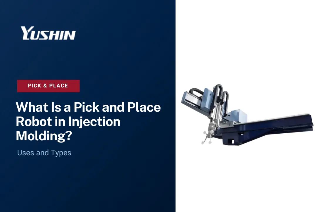

A pick and place gantry is a Cartesian robot that moves along fixed linear axes to transfer parts from one defined position to another. The system is programmed with defined pick and placement positions and repeats that motion according to the robot's specified motion and repeatability capabilities.
This guide covers what pick and place gantry systems are, how the motion works, what the end-of-arm tooling does, and where these systems fit inside a plastics injection molding operation. It also covers what to define before you select a robot architecture, because gantry and Cartesian designs are not automatically the right answer for every application.
What Is a Pick and Place Gantry?

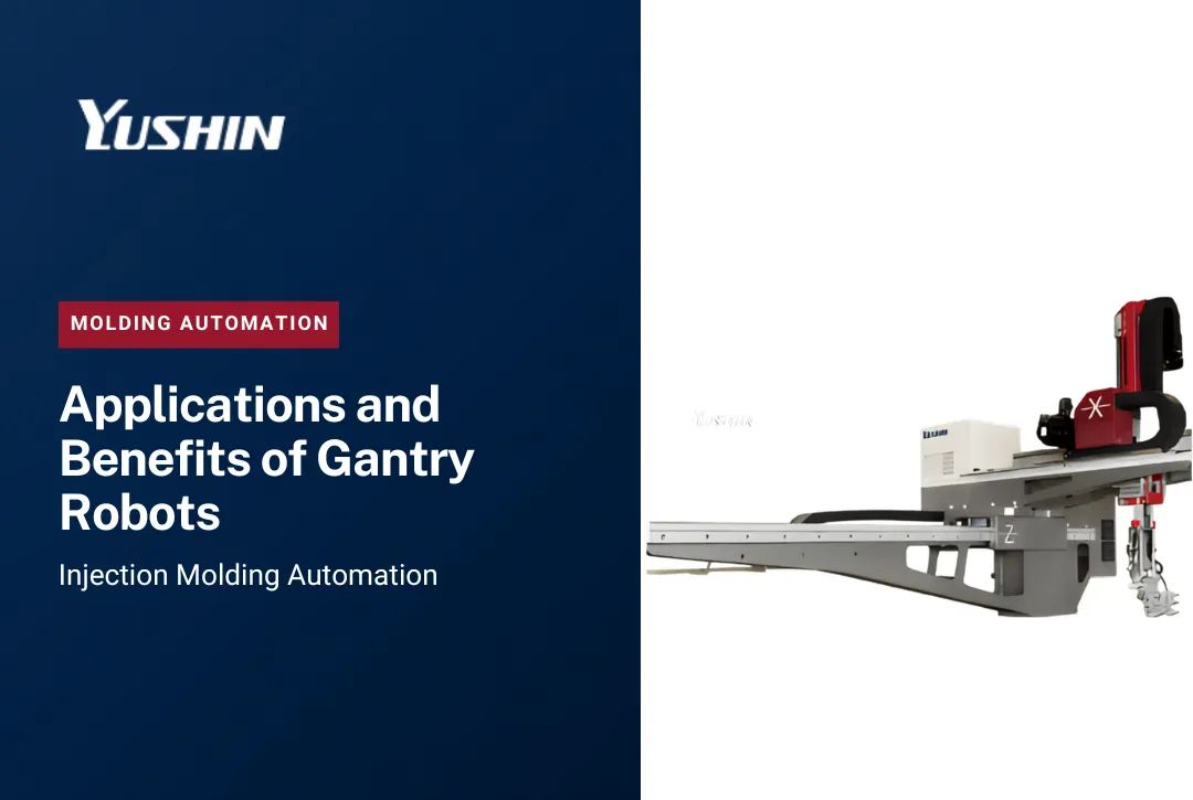
A pick and place gantry is a linear-axis robot built on a Cartesian coordinate frame. Three orthogonal axes - X, Y, and Z - define the robot's workspace. The end-of-arm tooling (EOAT) moves along those axes in straight lines to reach a programmed pick position, secure the part, and travel to the programmed placement position before releasing.
Cartesian and gantry systems use linear-axis motion rather than the rotary-joint motion of an articulated robot. This can make them a practical choice for applications where the pick position, placement position, and required path are fixed and repeatable.
How Cartesian and Linear-Axis Motion Works
Each axis is driven by a servo motor coupled to a linear drive mechanism - commonly a belt drive for long-stroke, high-speed runs, or a ball screw for shorter strokes where thrust and positional stiffness matter. An absolute encoder on each axis reports position back to the motion controller continuously, so the system always knows exactly where the EOAT is sitting.
When the controller commands a move, it coordinates the active axes according to the programmed motion path. Yushin's FRA Series, for example, uses Arc Motion Control to create smooth curved movement across robot axes, which Yushin positions as a way to shorten cycle time while controlling vibration.
The key distinction between a true gantry configuration and a cantilevered Cartesian robot is how the primary traverse axis is supported. In a cantilevered design, the traverse beam is supported from one end only. In a true gantry, the beam rides on two parallel linear rails, distributing the load symmetrically. This structural difference allows gantry configurations to handle heavier payloads and longer stroke lengths without deflection.
What the EOAT Does
The end-of-arm tooling is the interface between the robot and the part. It does the actual picking and placing. Everything upstream - the servo axes, the motion controller, the frame - exists to position the EOAT accurately at the right moment.
Common EOAT types in molding applications:
- Vacuum cup arrays for thin-wall containers, closures, and smooth-surfaced parts where grip force must stay controlled
- Mechanical grippers for structural parts with consistent geometry and adequate grip surfaces
- Double-wing tooling for extracting parts from multi-cavity molds simultaneously, or for separating parts from runners at the take-out position
EOAT weight affects the payload carried by the robot and can influence acceleration, deceleration, vibration, and settling behavior. EOAT should therefore be engineered to provide the required rigidity and gripping performance without unnecessary mass. Yushin provides application-specific EOAT as part of its molding automation work.
How the Pick Position Transfers to the Placement Position
The motion controller stores the required pick, clearance, and placement positions as part of the programmed sequence. During molding, the robot and injection molding machine exchange the required process and interlock signals before the robot enters the mold area. The exact signal logic and axis sequence depend on the IMM, robot configuration, mold, and application.
At the placement position, the EOAT releases the part - onto a conveyor, into a box, onto a fixture, or to secondary equipment. The robot then returns to the home position and waits for the next cycle signal from the IMM.
Yushin's E-touch controller series uses a touchscreen teach interface and Lead-Through Teaching (LTT) so operators can establish or adjust pick and placement positions directly on the floor without specialized programming expertise.
Gantry and Cartesian Architecture in Injection Molding

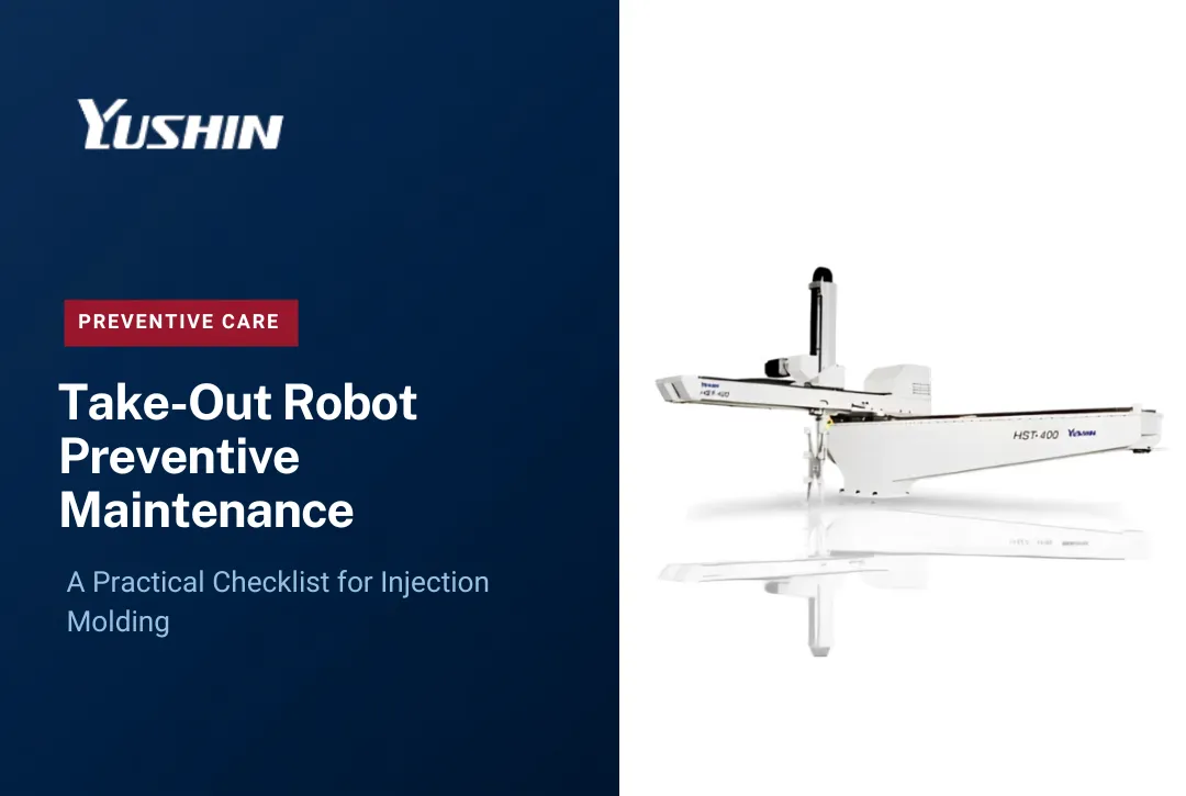
Injection molding take-out robots are often described as Cartesian or traverse robots because they share the same linear-axis motion principle as gantry systems. They move along X, Y, and Z axes, they have programmed pick and placement positions, and they use EOAT to handle parts.
However, not every take-out robot is a gantry in the structural sense. Most injection molding traverse robots use a cantilevered arm design - the traverse beam extends from one side of the machine frame rather than spanning between two parallel rails. This configuration is purpose-engineered for the physical constraints of injection molding: the robot must enter the mold area from above (or from the side for side-entry designs), clear the mold halves as they open, and retract before the mold closes for the next shot.
True overhead gantry configurations - with dual-rail support spanning multiple axes of travel over a larger work area - appear more commonly in downstream automation: conveyor loading, tray or fixture stations, palletizing, and multi-press cell configurations that require the robot to serve a wider horizontal footprint.
Yushin America's YD/YD2 Series standard take-out robots use servo-driven Cartesian motion for injection molding take-out across a broad range of machine sizes and applications. They apply linear-axis pick-and-place motion to the specific access, stroke, payload, and cycle requirements of a molding cell. Calling every traverse take-out robot a "gantry robot" can create confusion because the structural configuration may differ from a dedicated overhead gantry system.
Pick and Place Applications in Injection Molding

The pick-and-place motion cycle - enter mold, pick part, exit, place part - applies across a wide range of tasks in a molding operation. Here is where these systems are typically deployed:
Molded part take-out. The fundamental application. The robot enters the open mold, removes the finished part from the cavity or from the ejector pins, retracts, and deposits the part downstream. Consistent, repeatable take-out is the baseline requirement for any automated molding cell.
Part and runner separation. In cold-runner molds, the sprue and runner system is ejected with the part. The take-out robot or a dedicated sprue picker - such as Yushin's HOP Five or N-HOP swing-type pickers - separates the runner at the take-out position or deposits parts and runners to separate positions for segregation.
Placement onto conveyors. After take-out, parts are deposited onto a belt conveyor for downstream processing or inspection. The placement position may be a specific lane, orientation, or spacing on the belt depending on what follows.
Tray or fixture loading. Parts requiring secondary operations - insert assembly, inspection, overmolding, or decoration - are placed into fixtures or trays at a defined position and orientation. Positional accuracy at placement matters as much as accuracy at pick.
Inspection presentation. Vision inspection systems require parts to arrive at a defined position in a defined orientation. The robot serves as the presentation mechanism, placing each part in the same location and orientation for the camera system.
Degating. Gate cutting or degating can be integrated into the take-out motion, with the EOAT passing the part through a gate-cutting station before final placement. Yushin's Adaptive Motion Control on the FRA Series adjusts the motion profile at gate-cut positions to reduce stress on both the part and the tooling.
Assembly handoff. In multi-shot or insert molding operations, the robot transfers a partially completed part from one station to another, maintaining orientation for the next process step.
Box loading. Parts are counted and loaded into shipping boxes or returnable containers at the end of the cell. Placement accuracy and consistent layering keep parts from nesting or tangling during transit.
Other downstream placement tasks. Stacker loading, sortation by cavity, label verification drops, and palletizing all follow the same pick-and-place motion logic applied to different destination positions.
Gantry vs. Articulated Robot: Choosing the Right Architecture

A Cartesian or gantry architecture is not automatically superior to a 6-axis articulated robot. The correct choice depends on what the motion actually requires.
Gantry and Cartesian systems perform best when:
- The pick position and placement position are both fixed and repeatable across every cycle
- The motion path stays largely linear - in, pick, out, place
- Payload and stroke requirements fit within the robot's rated envelope
- High cycle rates are required with consistent positioning accuracy
- Floor space below the robot must remain accessible
Articulated robots perform better when:
- The task requires complex reorientation between pick and placement (flipping a part, rotating through multiple angles)
- The pick location varies and requires vision-guided adaptive positioning
- The robot must reach around obstacles or into confined spaces from multiple angles
- The cell layout changes frequently and flexibility is a priority over peak cycle rate
For many injection molding take-out applications, the required motion is largely linear and repeatable, which makes Cartesian traverse robots a practical architecture. Where significant controlled reorientation or a more complex reach path is required, another configuration - such as additional wrist axes or an articulated robot - may be appropriate.
Yushin's NC Servo Wrist Units can add controlled rotational axes to suitable take-out robot configurations where the application requires additional part or EOAT orientation. Final suitability depends on the required motion, robot configuration, payload, cycle time, and mold access.
Selection Criteria for Gantry and Cartesian Pick and Place Systems
Getting the application requirements defined before selecting a robot is more important than any individual product specification. Here are the criteria that drive the decision:
Work envelope. The robot must reach both the pick position inside the mold area and every placement position outside it within its rated stroke. Define all positions before shortlisting hardware.
Stroke lengths. X, Y, and Z stroke requirements are set by the distance between the pick position and the farthest placement position, plus clearances for tooling and mold access. Stroke and rigidity interact: longer strokes on cantilevered designs require more attention to deflection.
Total payload including EOAT. Payload must account for the molded part or parts plus the EOAT and other components carried by the robot. Payload should be checked against the actual operating configuration rather than part weight alone.
Pick and place positions. Fixed positions simplify programming and allow the use of simpler Cartesian traverse robots. Variable or flexible positioning requirements push toward vision-guided systems or articulated robots.
Required cycle time. Robot take-out time is a direct component of total molding cycle time. A robot that cannot complete take-out within the allotted window constrains production. Define the maximum acceptable take-out cycle time before evaluating speed specifications.
Repeatability. How much positional variation can the application tolerate at the placement position? Inspection fixture loading and assembly handoff require tighter repeatability than bulk conveyor drops.
Part orientation. If the part must arrive at the placement position in a different orientation than it leaves the mold, the robot architecture must include a mechanism to execute that rotation - either a servo wrist unit or a reorientation station.
Mold access requirements. Side-entry molds, vertical presses, and tight clamp-end cells each impose different access geometry constraints. The robot architecture must match the physical access path, not the other way around.
Overhead vs. floor space. Traverse robots mount above the press and claim overhead space. Side-entry robots enter from the fixed half of the mold and claim side clearance. Downstream gantry stations claim overhead space above the conveyor or placement area. Understand what is available before committing to a mounting configuration.
Downstream handoff. What happens immediately after placement? Conveyor speed, fixture location tolerance, box positioning, and inspection system timing all affect how the placement position and timing must be programmed.
Integration with the IMM. The robot must receive accurate cycle signals from the injection molding machine controller and respond within defined timing windows. Compatibility with the press's I/O protocol and safety circuit is a specification requirement, not an afterthought.
Yushin America's Cartesian Take-Out Robot Platform
Yushin America provides several take-out robot platforms for different injection molding requirements. Robot selection should be based on the actual IMM, mold, part, EOAT, payload, stroke, cycle time, and downstream process rather than selecting a model family first.
YD/YD2 Series: Standard take-out robots covering a broad range of molding applications and machine sizes.
HST/HSA: High-speed take-out platforms for applications where take-out time, moving mass, vibration, and settling behavior are significant constraints.
FRA Series: High-end take-out robots with verified features including Active Vibration Control, Arc Motion Control, and Adaptive Motion Control. INTU LINE production-monitoring capability is also associated with the FRA platform.
MKA-2000S: A large 3-axis Cartesian take-out robot for injection molding machines of 1,500 tons or larger, with published payload capability up to 50 kg including EOAT.
Custom end-of-arm tooling should be evaluated together with the robot because EOAT weight, geometry, gripping method, mold access, and downstream requirements all affect the final automation configuration.
To review an application, contact Yushin America.
Define These Before Selecting a Robot Architecture
Before evaluating any robot product line, define the following for your application:
- Pick position - exact location, orientation, and timing relative to the mold open signal
- Placement position - exact location, orientation, and any sequencing requirements at the destination
- Total payload - part weight plus all EOAT components, cables, and wrist hardware
- EOAT type - vacuum, mechanical, or combination, based on part geometry and material
- Required motion - is the path linear and fixed, or does it require reorientation?
- Cycle time - maximum acceptable take-out time as a fraction of total molding cycle
- Available workspace - overhead clearance, floor footprint, and side access constraints
These seven inputs determine whether a Cartesian traverse robot, an overhead gantry station, an articulated robot, or a cobot is the appropriate architecture for the task. Getting them defined before opening a product catalog saves specification time and avoids costly mismatches during installation.
Frequently Asked Questions
What is the difference between a gantry robot and a Cartesian take-out robot for injection molding?
Both use linear X, Y, and Z axes to move the EOAT between pick and placement positions. A true gantry spans its primary traverse beam between two parallel rails for heavier payloads and longer strokes. Most injection molding take-out robots use a cantilevered arm design that is purpose-engineered for mold-area access, clearance around mold halves, and the specific stroke and cycle time demands of a molding cell. The motion principle is the same; the structural configuration and application-specific engineering differ.
How do I know if my application needs a Cartesian traverse robot or an articulated robot?
If the pick and placement positions are fixed and the required motion is largely linear, a Cartesian traverse robot may provide a direct solution for an injection molding application. If the task requires complex reorientation, variable pick positions, or reach around obstacles, an articulated robot or a traverse robot with appropriate orientation axes may be better suited. Compare the architectures against the actual payload, motion, cycle time, workspace, and downstream requirements rather than assuming one is universally better.
What payload should I specify for a pick and place robot in an injection molding cell?
The complete EOAT assembly can contribute a meaningful portion of the total carried load. Calculate payload using the actual production configuration, including all parts, tooling, wrist hardware, fittings, and other carried components, and confirm the required margin against the selected robot's specifications.
Can a standard traverse take-out robot handle downstream placement tasks like tray loading or box loading?
Yes, provided the placement position and required orientation fall within the robot's rated stroke and the cycle time budget permits the additional travel. For downstream placements that extend significantly beyond the press footprint, a dedicated downstream gantry or conveyor station fed by the take-out robot is often more efficient than extending the take-out robot's stroke. The right answer depends on the distance, required accuracy, and whether the downstream placement must occur within the molding cycle or can be buffered.
What repeatability should I expect from a Cartesian pick and place robot for injection molding?
Repeatability varies by robot model, payload, stroke, EOAT, motion profile, and operating conditions. For inspection-fixture loading or precision downstream placement, use the published specification for the exact robot configuration and confirm that it is appropriate for the application. Vibration, EOAT mass, stroke, and motion profile should also be considered when evaluating placement performance.
How does EOAT affect cycle time in a pick and place application?
EOAT mass directly affects how aggressively the robot can accelerate and decelerate. Heavier tooling requires reduced acceleration limits to avoid damaging the part, stressing the robot arm, or causing the EOAT to deflect at the pick position. Every kilogram of unnecessary tooling weight is a cycle time penalty. Lightweight EOAT engineering - using aluminum structures, optimized vacuum circuit layouts, and minimal material at maximum reach - is one of the most effective cycle time improvements available without changing the robot's rated speed specifications.