
A molding machine robot is automation used with an injection molding machine to remove molded parts, runners, or other items from the mold area and transfer them to the next required position or process. Many standard injection-molding take-out robots use a Cartesian or traverse architecture, while side-entry, vertical-machine, and other robot configurations are used where the application requires a different motion path.
Before going further, a few common points of confusion are worth clearing up:
- A molding machine robot is not a robot that manufactures the injection molding machine.
- It is not the injection molding machine itself.
- It is not automatically an articulated six-axis robot; the appropriate architecture depends on the molding application.
- It is not software automation.
This article explains what the robot does on every molding cycle, how it communicates with the injection molding machine (IMM), and what a buyer needs to specify to select the right one.
What the Robot Does on Every Molding Cycle

This is the sequence that repeats on every shot. Understanding each step explains why robot selection and setup details matter.
1. The IMM completes the molding cycle. The plastic cools and solidifies in the mold cavity. The machine is ready to open.
2. The mold opens to the set mold-open position. The movable platen travels to its programmed open position. The mold must be fully open before the robot can safely enter.
3. The robot and IMM satisfy the required entry conditions. The robot and injection molding machine exchange the required process and safety interlock signals before robot entry. The exact signal arrangement depends on the IMM, robot controller, and cell configuration. The automation sequence must prevent robot entry until the required mold and machine conditions have been satisfied.
4. The robot enters the mold area via its programmed traverse path. The robot arm descends (or enters from the side, on a side-entry configuration) along its programmed path. Stroke length, reach, and clearance are all defined by the mold and part geometry.
5. The EOAT grips the molded part and/or sprue/runner. End-of-arm tooling - whether vacuum cups, mechanical grippers, or a combination - secures the part as designed. Multi-cavity tools may handle multiple parts simultaneously. On some applications, the EOAT handles the part and the sprue/runner with separate gripper zones.
6. The robot extracts the part and clears the mold area. The robot retracts along its programmed path, carrying the part out of the mold space. The required robot-clear and machine interlock conditions must be satisfied before the molding sequence proceeds.
7. Mold-close conditions are satisfied. Once the required robot and IMM interlock conditions are confirmed, the molding sequence can continue. The exact signal logic depends on the machine, robot controller, and integration configuration. Robot-clear time remains important because unnecessary delay in leaving the mold area can extend the overall molding cycle.
8. The robot transfers the part to the downstream position. The robot deposits the part on a conveyor, places it in a fixture, presents it to an inspection station, or performs another downstream action depending on the cell design.
9. The cycle repeats.
Each step in this sequence has a timing dependency. A robot that enters late, exits slowly, or fails to confirm its clear status correctly adds time to every cycle. Multiply that across thousands of cycles per shift and the impact on output is significant.
Robot/IMM Communication and Synchronization

The robot and the IMM exchange signals through electrical interlocks to coordinate the entry/extract/clear/close sequence. The robot controller receives signals from the IMM - including mold-open position and ejector status - and sends confirmation signals back, including robot-clear.
In practice, the robot controller manages production data, cycle monitoring, alarm handling, and error response as part of this coordination. Yushin's E-touch controller series is designed around this type of integrated machine-tending operation.
Interface requirements vary by IMM brand, model, and controller generation. Interface requirements should be confirmed for the specific IMM, robot controller, and cell before equipment is specified or purchased. Do not assume compatibility based on general descriptions.
What Buyers Must Specify: Selection Factors

Selecting a molding machine robot requires more than matching it to press tonnage. The following factors all feed into a correct specification.
IMM clamp force Tonnage is a starting point for initial robot matching, but it is an indirect indicator at best. Two presses with identical tonnage can have very different mold sizes, tie-bar spacing, and open-daylight dimensions. Do not rely on tonnage alone.
Mold dimensions The physical size of the mold determines the robot stroke and reach needed to enter the mold area, reach the part, and exit cleanly. Mold height, width, and depth all factor in.
Part dimensions The part size determines clearance requirements on entry and exit. Tall or wide parts require more vertical stroke or kick (horizontal reach). Long or cantilevered parts require careful path planning to avoid tie-bar interference.
Part and EOAT payload The robot must carry the combined weight of the part, the EOAT itself, and any fixtures attached to the wrist. Undersizing payload results in dropped or damaged parts. Always calculate total payload - not just part weight.
Vertical stroke The robot must reach into the mold cavity with adequate clearance above and below the part. Insufficient vertical stroke means the robot cannot reach the part; excessive stroke adds unnecessary travel time.
Kick / horizontal reach For deep molds, offset cavities, or multi-cavity layouts where the part is not centered under the robot beam, horizontal kick reach is required. This is a common oversight in early specification.
Traverse distance The horizontal distance from the mold to the downstream placement point - conveyor, fixture, inspection station, or packing area - defines the required beam length and traverse stroke.
Mold-open window and required take-out time The available time between mold-open and mold-close is finite. The robot must enter, extract, and clear within this window. Required take-out time is the robot's contribution to overall cycle time and must be matched to the IMM's molding cycle.
Part and runner handling Some applications require the part and the sprue/runner to be handled separately - deposited to different locations, cut at the gate, or presented to different downstream stations. EOAT design and robot programming both depend on this requirement.
EOAT design Tooling must be engineered for the specific part geometry, cavity count, material, and downstream requirement. Yushin offers custom end-of-arm tooling engineered for applications including double-wing demolding, insert molding, in-mold labeling, and sprue/product separation.
Orientation and placement requirements Does the part need to arrive at the downstream station in a specific orientation? Does it need to be placed in a nest, a tray, or a fixture with a defined position? These requirements affect wrist axes, programming, and EOAT design.
Downstream placement Conveyor drop, fixture placement, inspection station, assembly cell, tray loading, and box loading each have different requirements for robot reach, placement accuracy, and cycle timing.
Floor and overhead space Cell layout constraints - including tie-bar clearance, overhead obstructions, and floor space available on either side of the press - affect which robot configurations are physically feasible.
Controller usability Ease of programming, changeover, and production monitoring affects operating cost over the life of the equipment. Controllers with graphical simulation, clear alarm handling, and accessible production data reduce the time operators spend troubleshooting and reconfiguring.
Changeover requirements If the cell runs multiple molds or parts, the robot must be reconfigured quickly. Quick-change EOAT mounting, stored programs, and accessible wrist positions all affect changeover time.
Service and parts support Local availability of technical support, OEM spare parts, and trained service personnel affects uptime over the robot's service life.
Do not select a molding machine robot from press tonnage alone. Mold size, part geometry, payload, stroke, cycle time, and downstream requirements all determine whether a specific robot is correct for the application.
Yushin Take-Out Robot Range
Yushin America's take-out robot lineup covers the range of IMM sizes and application types that buyers typically encounter:
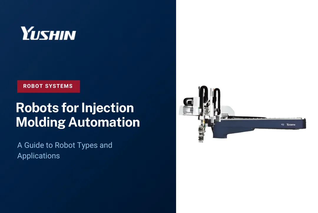
YD/YD2 standard take-out robots support standard molded-part take-out applications across a broad range of injection molding machine sizes. Suitability depends on the specific IMM, mold, payload, stroke, cycle-time, and downstream handling requirements.
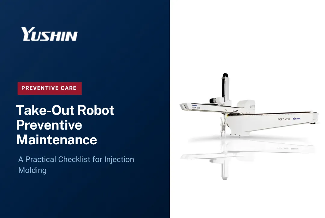
HST high-speed take-out robots are purpose-built for verified high-speed applications where cycle time and settling time are critical. The HST is not a standard robot with larger motors - it is a distinct platform designed from the ground up for fast-cycle packaging and closure applications. Confirmed application data is needed to specify the HST high-speed take-out robot correctly.
Side-entry robots serve applications where mold access or cell layout calls for horizontal robot entry rather than top-entry. In-mold labeling (IML) cells and micromolding cells are common examples where a side-entry configuration is the correct choice.
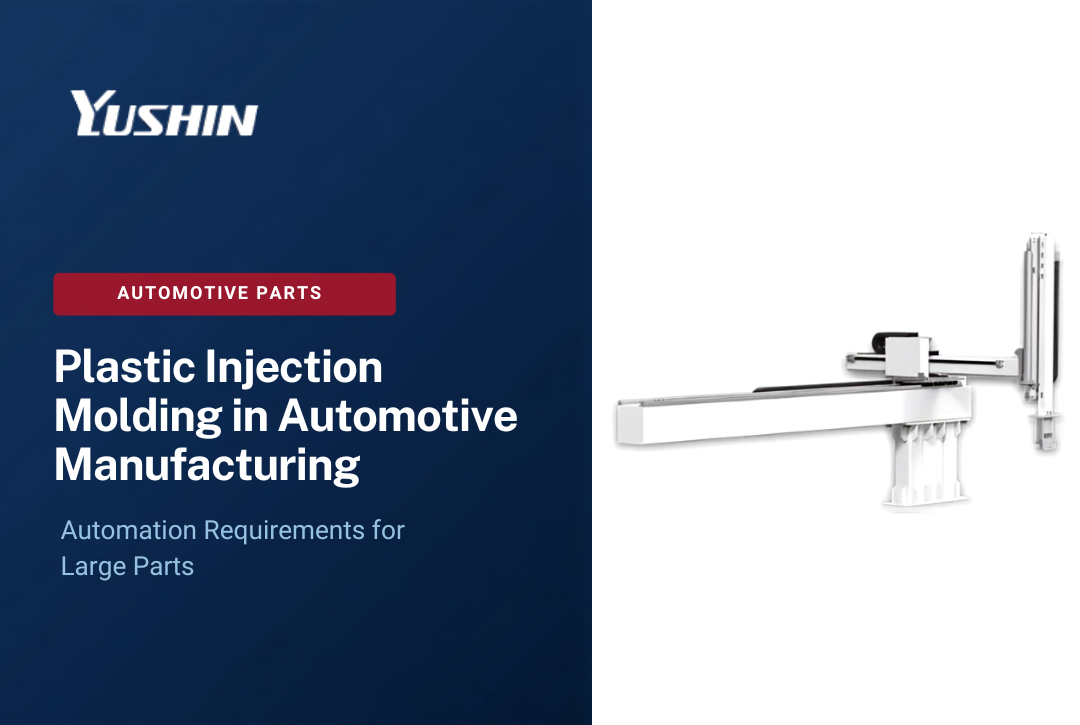
MKA-2000S is a large take-out robot developed for very large molding applications. Yushin's published information positions it for injection molding machines of 1,500 tons or larger. Final suitability depends on the actual machine, mold, part dimensions, EOAT, payload, stroke, and cycle requirements.
Sprue pickers are used where the automation requirement is focused on removing a sprue or runner rather than performing complete molded-part take-out and downstream handling. Whether a sprue picker or a full take-out robot is appropriate depends on the mold, runner system, part-handling method, and required automation scope.
Vertical-IMM robots are for rotary-table and vertical-press machines where the machine orientation requires a different robot geometry than a standard top-entry traverse.
The right starting point is not the robot model - it is the IMM, mold, part, and cycle requirements. The robot model follows from that specification.
Beyond Take-Out: Downstream Automation

The molding machine robot does not have to stop at extracting the part from the mold. The same robot - or an integrated downstream system working in coordination with it - can feed:
- Cooling conveyors to allow parts to stabilize before handling or inspection
- Vision inspection stations to check part presence, gate quality, or dimensional conformance
- Degating or trimming stations to separate the part from the runner at the gate
- Assembly fixtures where the molded part is combined with another component immediately after take-out
- Part packing stations for direct-to-tray or direct-to-box placement
- Box loading where parts are deposited into shipping containers
- Palletizing for end-of-line stacking and load building
Connecting take-out with appropriate downstream operations can reduce intermediate handling and create a more coordinated molding cell. Depending on the complete cell design, fault handling, safety system, material supply, inspection requirements, and downstream automation, this integration may also support reduced-attendance or unattended production. Yushin America provides systems integration support for cells that extend beyond part take-out into downstream automation.
Conclusion
A molding machine robot is a specific piece of equipment with a specific job: enter the mold area on cue, extract the part, clear the mold, and transfer the part downstream - cycle after cycle, shift after shift.
Getting the specification right requires working through IMM clamping force, mold dimensions, part size, total payload, required stroke, cycle time requirements, mold access configuration, EOAT design, and downstream placement before choosing a robot model. Tonnage is a starting point, not a specification.
Contact Yushin America to review your IMM, mold, part, EOAT, stroke, cycle time, mold access, and downstream placement requirements with an applications engineer before selecting the take-out robot.
Frequently Asked Questions
What is the difference between a molding machine robot and a sprue picker?
A take-out robot extracts the full molded part from the mold cavity and transfers it to a downstream position. A sprue picker removes only the sprue or runner from the mold - typically in applications where an operator handles the finished part. A sprue picker is simpler and lower in cost but cannot perform full part handling, orientation, or downstream placement.
How do I know if my existing injection molding machine can accept a take-out robot?
The key factors are mold-open daylight (the robot needs enough vertical clearance to enter and exit), tie-bar spacing (the robot must fit between or above the tie bars), and whether the IMM has a compatible electrical interface for robot interlocking. Interface requirements should be confirmed for the specific IMM, robot controller, and cell. Contact a Yushin applications engineer to review your machine before specifying a robot.
Can a molding machine robot handle multiple cavities at the same time?
Yes. Multi-cavity EOAT can grip parts from several cavities simultaneously on a single robot arm entry. The tooling is engineered for the specific cavity layout and part geometry. The robot's payload rating must account for the combined weight of all parts plus the tooling itself.
What causes a robot to slow down or become a cycle-time bottleneck?
Common causes can include insufficient robot speed or stroke for the application, settling time after fast motion, EOAT weight, unnecessary robot travel, or a programmed sequence that does not fit the available molding-cycle window. Reviewing the complete path - entry, extraction, mold clearance, transfer, release, and return - against the actual IMM cycle helps identify where robot motion may be contributing unnecessary time.
What is end-of-arm tooling and why does it matter for take-out robot selection?
End-of-arm tooling (EOAT) is the gripper or fixture attached to the robot wrist that contacts and holds the molded part. It must be designed for the specific part geometry, material, cavity count, and downstream placement requirement. EOAT that is wrong for the part causes dropped parts, scrap, and cycle-time problems. The robot frame and the EOAT must be specified together - not independently.
How far in advance should I involve a robot supplier when planning a new mold or press?
As early as possible - ideally at the mold design stage. Mold-open travel, ejector stroke, gate location, and parting-line orientation all affect what the take-out robot must do and how the EOAT must be designed. Designing the mold and the automation cell together avoids the need to retrofit a robot to a mold that was not built with automation in mind.