
Plastic closures are commonly produced in high-output, multi-cavity injection molding applications. In these cells, the molding machine is only one element of the production system. The take-out robot, end-of-arm tooling (EOAT), part detection, downstream handling equipment, and synchronization between each step all affect whether the complete cell can maintain its required production rate.
This article explains how injection moulding bottle caps works, then focuses on what that production environment actually demands from the automation system around the press.
How Injection Moulding Produces Bottle Caps

Injection moulding bottle caps follows the same core sequence as any thermoplastic injection process: resin pellets are fed into a heated barrel, melted by screw rotation and barrel heat, then injected under pressure into a closed mold. The mold holds the melt at shape while cooling channels extract heat, and once the part has solidified sufficiently the mold opens and ejection occurs.
What distinguishes closure molding from most other injection applications is the combination of high cavitation, thin walls, and short cycle times:
- Multi-cavity production - one molding cycle may produce many closures simultaneously, so the EOAT and downstream equipment must be designed around the actual cavity layout and output rate.
- Short production cycles - where the molding process runs quickly, robot entry, part pickup, mold clearance, and downstream transfer must fit within the available cycle-time budget.
- Material requirements - closure materials vary by product design, sealing requirements, application, and molding process. The automation system should therefore be engineered around the actual part and process rather than assuming a universal closure configuration.
The result is a high-pressure, fast-cycling environment where each mold open-and-close event must be used productively. Any delay in part removal - whether caused by slow robot motion, incomplete part pick-up, or settling time after fast movement - reduces effective output.
Three Distinct Operations: Molding, Take-Out, and Cap Closing

Before discussing automation requirements in detail, it helps to separate three operations that are sometimes conflated:
Cap molding is the injection molding process itself - the IMM closes, injects, cools, and opens. The output is a molded plastic closure sitting in the open mold.
Take-out and handling is the robot's job: entering the open mold after ejection, picking every part from every cavity simultaneously, withdrawing before the mold closes again, and transferring the parts to a downstream station or conveyor. This is where EOAT engineering, vacuum confirmation, part detection, robot speed, and settling time all become critical.
Cap closing or assembly is a separate downstream operation involving a molded closure and another component or product. The exact operation and equipment depend on the application. It should not be confused with molding the cap itself or removing it from the injection mold.
These three operations are distinct. The robot's task ends when parts have been reliably transferred out of the mold area. Everything downstream - inspection, packing, and ultimately capping lines - is separate from the molding cell.
What High-Cavitation Closure Molding Demands from the Take-Out Robot
When a mold opens with 32, 48, or 64 cavities, every one of those parts must be removed before the mold can close again. This creates a set of engineering requirements that are more demanding than most single- or low-cavity applications.
Multi-Cavity EOAT

The take-out robot's end-of-arm tooling must reach every cavity simultaneously. For a 64-cavity mold arranged in a grid pattern, the EOAT must position a vacuum cup - or equivalent pick point - at each cavity location with sufficient accuracy that suction is established before withdrawal begins. The EOAT structure must be rigid enough to maintain those positions under the inertia loads of fast robot motion.
Yushin engineers application-specific EOAT for closure molding. As one example of this work, Yushin has built a 64-cavity EOAT incorporating venturi vacuum generators and individual sensors at each pick point - a configuration designed to confirm that every cup has established contact and hold before the robot withdraws. This is not a universal configuration for all cap applications; it is an example of the engineering that high-cavitation closure molding requires. Learn more about Yushin's end-of-arm tooling engineering.
Vacuum and Sensor Requirements
Part-presence detection is an important design consideration in multi-cavity EOAT. Depending on the application, sensors can be used to verify that the expected parts have been captured before the molding sequence continues. A missing or incorrectly picked closure can affect downstream counts and, in some situations, create a risk if a part remains in the mold area.
Yushin has built closure EOAT using venturi vacuum generation and individual sensors at multiple pick points, but the exact sensing and interlock arrangement should be engineered for the specific mold, EOAT, robot, and IMM.
Take-Out Speed and the Mold-Open Window
In a short-cycle molding cell, the time the mold stays open is a finite window. The robot must enter the mold space, position the EOAT over the cavities, confirm pick-up, and clear the mold area entirely before the press can close and begin the next shot. Any robot motion that extends beyond that window adds directly to cycle time.
This places a real premium on robot speed - but speed alone is not sufficient. A robot that reaches high peak velocity but requires a long settling time before the EOAT is stable enough to make contact is no faster in practice than a slower robot with better vibration damping.
Robot Settling and Vibration

After a fast traverse move, the robot arm and EOAT oscillate briefly before coming to rest. In high-speed closure molding, that settling time is not free - it is part of the mold-open window. If the robot moves fast but takes too long to damp out vibration before the EOAT engages the parts, the net result is either a positioning error (suction cups miss cavities or make partial contact) or the operator slows the robot deliberately to achieve reliable picks - giving back the speed advantage.
Structural rigidity in the robot arm reduces the amplitude of post-motion oscillation. Less moving mass means less inertia, which means oscillation decays faster. Active vibration control technology, where the controller actively counteracts residual motion rather than waiting for passive damping, shortens settling time further.
EOAT weight also matters here: a heavy end-of-arm tool on a fast robot increases the inertia load and extends settling time. Minimizing EOAT mass - while maintaining the rigidity needed for accurate cavity engagement across all pick points - is part of the design tradeoff Yushin addresses in application-specific EOAT engineering.
The HST High-Speed Take-Out Robot for Closure Molding

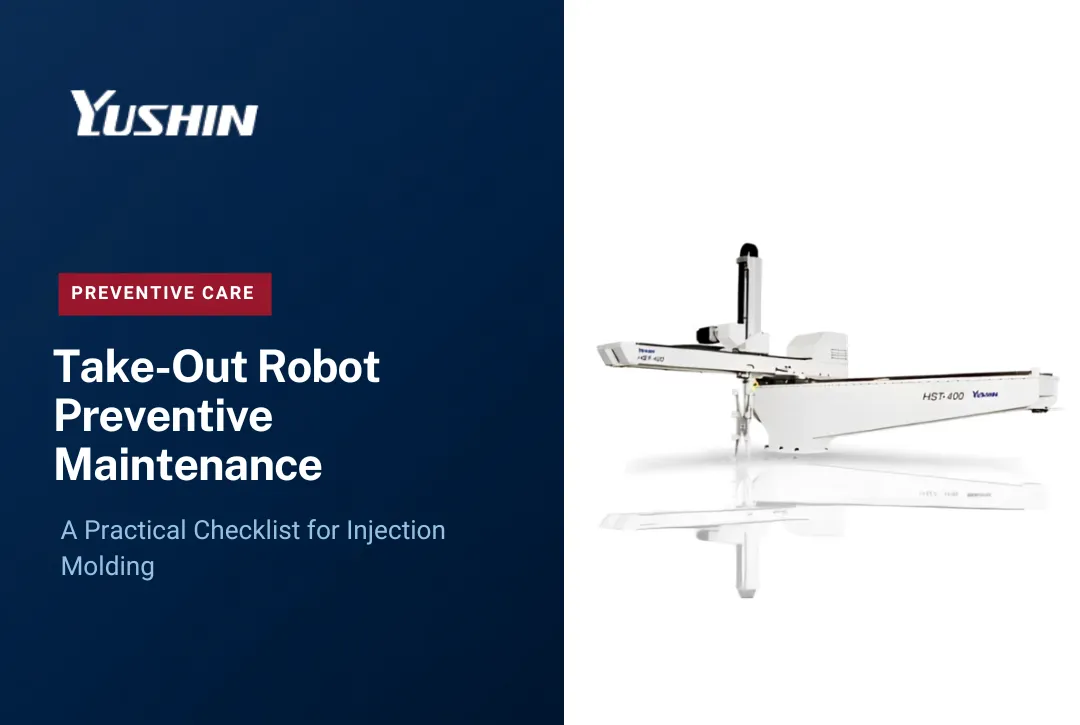
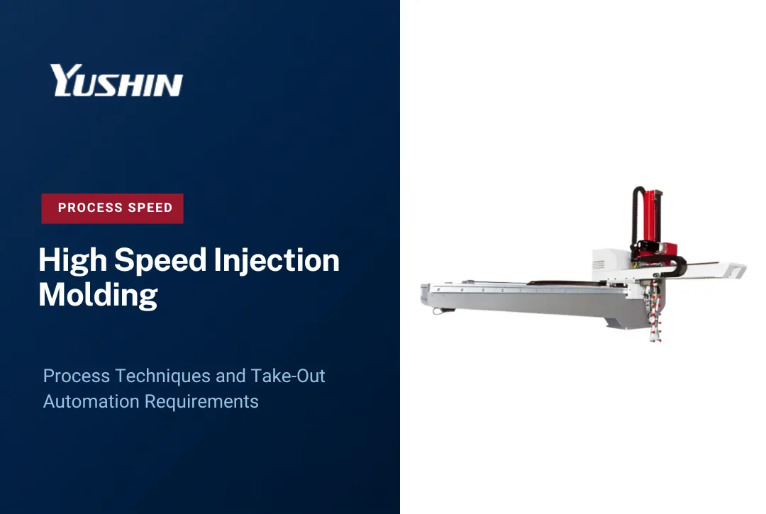
High-speed closure and packaging applications can place demanding requirements on robot acceleration, deceleration, structural rigidity, moving mass, EOAT weight, and settling behavior. Yushin's HST high-speed take-out robot is a purpose-built high-speed platform designed around these types of fast-cycle molding requirements.
The important distinction is that HST should not be described as a standard robot with larger motors. Its design incorporates reduced moving mass and structural/vibration-control measures intended to support fast, stable take-out motion.
EOAT remains part of the same engineering problem. A multi-cavity tool must be light enough for the robot's required motion while remaining sufficiently rigid to engage the actual cavity pattern consistently.
HST is not automatically the correct robot for every closure application. Standard YD/YD2 take-out robots or another Yushin configuration may be appropriate depending on cavity count, mold-open time, part and EOAT payload, IMM size, and required take-out time.
Final robot selection should therefore be based on the actual molding application rather than the fact that the molded part is a closure.
Cap Orientation, Cooling, and Downstream Handling
Reliable part removal is the beginning of downstream handling, not the end. Once caps leave the EOAT, several steps follow before they reach a filling or assembly line.
Part orientation - caps extracted from the mold arrive in a defined orientation relative to the EOAT. Whether they land on a conveyor open-side up, open-side down, or in a specific angular orientation depends on how the EOAT deposits them. Downstream sorting, inspection, and packing equipment typically require consistent orientation. The take-out sequence is designed with this in mind.
Cooling conveyors - thin-wall caps may still be slightly warm when they leave the mold. Conveyor length and airflow are used to complete heat dissipation before parts enter inspection or bulk handling. Releasing parts too early can cause deformation in bulk containers.
Inspection - vision systems or sensor arrays check for dimensional conformance, presence of tamper-evident bands, thread integrity, or surface defects. Inspection is integrated into the handling sequence between take-out and packing, and the robot's transfer sequence is designed not to disrupt part orientation before inspection.
Packing - caps go into bulk bags, gaylord boxes, or totes depending on the downstream application. Packing rate must be compatible with the press output rate; a packing station that cannot keep pace will back up the handling system and eventually interrupt the molding cell.
Downstream synchronization - the press, robot, conveyor, inspection, and packing systems all operate at different rates and with different response latencies. Keeping them synchronized so that no one element becomes the bottleneck requires matching throughput capacities at each stage. For end-of-line handling that includes palletizing, Yushin's PA Series compact palletizing robot is designed for integration into this kind of downstream sequence.
Yushin's EOAT and systems material includes examples of 38 mm and 45 mm cap-closing station work, showing that Yushin automation projects can extend into downstream closure-handling operations. The exact function and configuration of a cap-closing station are application-specific and should not be generalized to every closure-molding cell.
IML in Cap and Closure Molding
Not every bottle cap uses in-mold labeling. Most commodity closures - water bottle caps, standard pharmaceutical screw caps, beverage closures - are molded without any label component. IML is relevant only where the packaging design actually incorporates an in-mold label or decorative element as part of the closure.
Where the packaging design does use in-mold labeling, the automation sequence becomes more complex. A label must be placed in the mold cavity before injection, held in position during mold close and injection, and fused to the part surface as the resin flows. This requires either a dedicated label-insertion robot or a side-entry arm integrated into the molding cell, an additional motion sequence before each shot, and careful coordination between label placement and mold close timing. Cycle time and EOAT design are both affected.
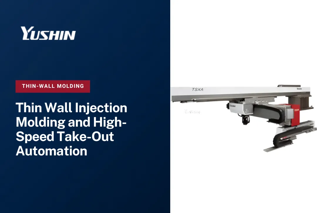
For cap and closure applications where IML is actually part of the design brief, Yushin's side-entry robots - including the TSXA for high-speed IML applications - are the relevant platform. The key point is that IML is an additional layer of automation complexity for the applications that need it, not a standard feature of closure molding.
Conclusion
High-output injection moulding bottle caps production is well understood as a molding process. The less-examined question is where the constraint actually lives in a running closure-molding cell. For many operations, the answer is not the press - it is the take-out robot's ability to clear high-cavity molds within a short cycle window, the EOAT's ability to reliably pick every part every cycle, the part detection system's ability to confirm a clean take-out before mold close, or the downstream handling system's ability to keep pace with press output.
If you are evaluating whether take-out speed, high-cavity EOAT engineering, part detection, downstream handling, inspection, or cap-closing automation is becoming the constraint in your closure-molding cell, contact Yushin America to review the application.
Frequently Asked Questions
How many cavities can a take-out robot EOAT handle for cap molding?
EOAT cavity capacity is application-specific. Yushin has built a 64-cavity EOAT example, but that does not establish a universal maximum or minimum for closure applications. The appropriate configuration depends on the mold cavity layout, robot payload, EOAT weight and rigidity, part-detection requirements, available mold-open time, and the complete take-out sequence.
Why does EOAT weight matter so much in short-cycle closure molding?
In a short-cycle molding cell, every fraction of a second counts. A heavier EOAT increases the inertia load on the robot, which extends the time required for the arm to settle after a fast traverse move. If settling time increases, either cycle time increases or the robot must slow down - both reduce output. Minimizing EOAT mass while maintaining the rigidity needed for reliable multi-cavity picks is a core engineering tradeoff in closure EOAT design.
How does the robot confirm that every cavity has been picked before the mold closes?
Part detection in multi-cavity closure EOAT is typically done with individual vacuum sensors or proximity sensors at each cup position. The robot controller reads the full sensor array after the pick move and before authorizing mold close. A missing part signal from any cavity triggers a fault condition so that the issue can be resolved before tooling is put at risk.
What is the difference between a take-out robot and a cap-closing robot?
A take-out robot removes molded caps from the injection mold and transfers them to downstream handling. Cap closing - applying a cap to a filled container - is a separate downstream operation that happens on capping equipment, not in the injection molding cell. The two operations use different equipment and occur at different points in the production process.
When does IML become relevant in closure molding?
IML is relevant only when the packaging design includes an in-mold label or decorative element fused to the closure during molding. Most commodity caps do not use IML. When IML is part of the design brief, it adds a label-insertion step to the automation sequence, requires a dedicated robot or side-entry arm for label placement, and affects cycle time and EOAT configuration.
What should I evaluate if my closure molding cell is not running at target output?
Start by separating the molding cycle from the automation cycle. If the press is ready to close but waiting for the robot to clear, the constraint is take-out - robot speed, settling time, or EOAT engagement time. If the robot is clearing in time but downstream handling cannot keep pace, the constraint is post-take-out: conveyor capacity, inspection throughput, or packing rate. Identifying which step is the actual bottleneck determines whether the solution is a faster robot, a redesigned EOAT, or changes to downstream equipment.