
Industrial robots show up in nearly every corner of manufacturing. Automotive plants use them for welding and painting. Electronics lines use them for precision assembly. These are real and well-documented applications of robots in industry.
But for plastics processors running injection molding cells, the relevant question is more specific: which robotic applications make sense inside and around my molding cell, and what does each one actually require? This article works through the full production sequence - from mold open to shipped pallet - and maps each automation opportunity to the task, the robot type, and the tooling involved.
The Injection Molding Cell as an Automation Sequence

An injection molding cell is not a single operation. It is a sequence of discrete tasks, each with its own timing, motion requirements, and part-handling demands. Robots can address most of them. The key is matching the right robot architecture and end-of-arm tooling (EOAT) to each specific task rather than assuming one robot type handles everything.
Molded-Part Take-Out
Part take-out is the foundational application. When the mold opens at the end of each cycle, a take-out robot enters the mold area, grips the molded part, withdraws, and releases the part to a downstream station or conveyor - all before the mold closes for the next shot.
The robot must complete this sequence within the available mold-open window without extending cycle time. Timing synchronization with the injection molding machine (IMM) is non-negotiable.
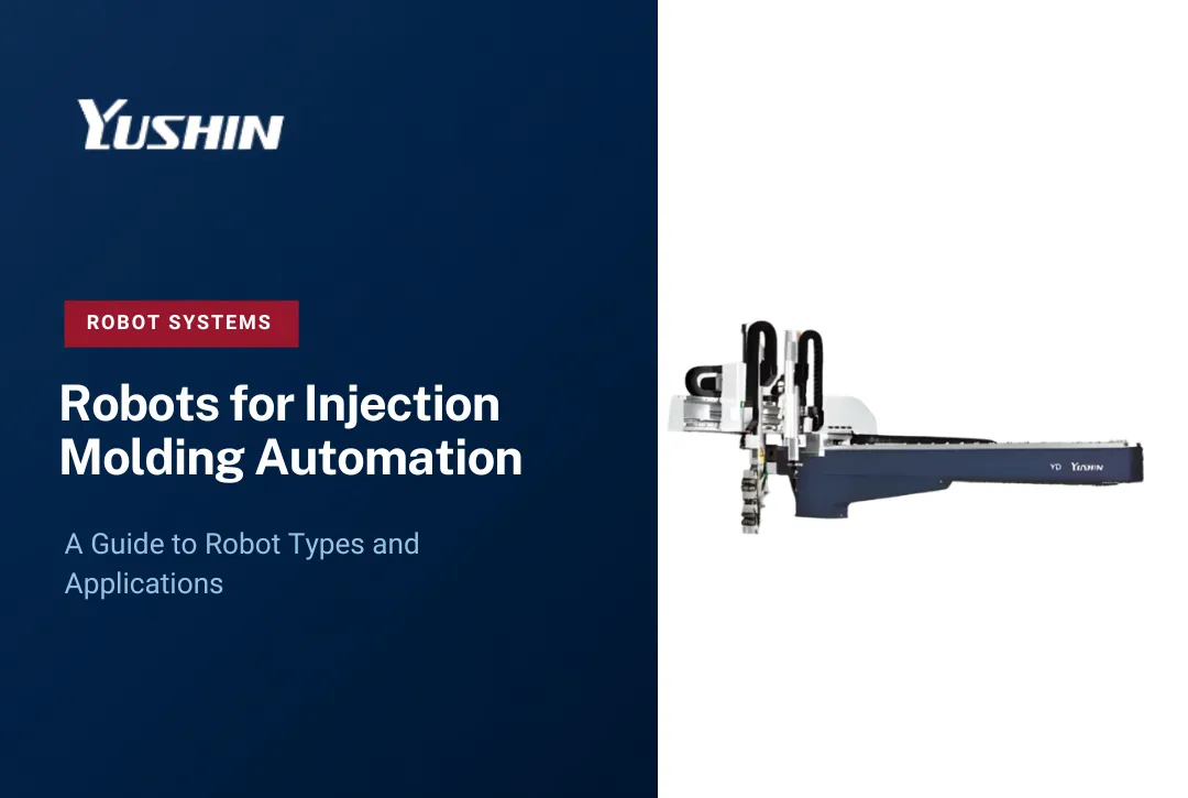
Standard take-out robots like the YD/YD2 Series cover a wide range of press tonnages and part sizes. They run on servo-driven traverse motion along the X, Y, and Z axes, with the EOAT engineered around the specific part geometry, weight, and material of each application.
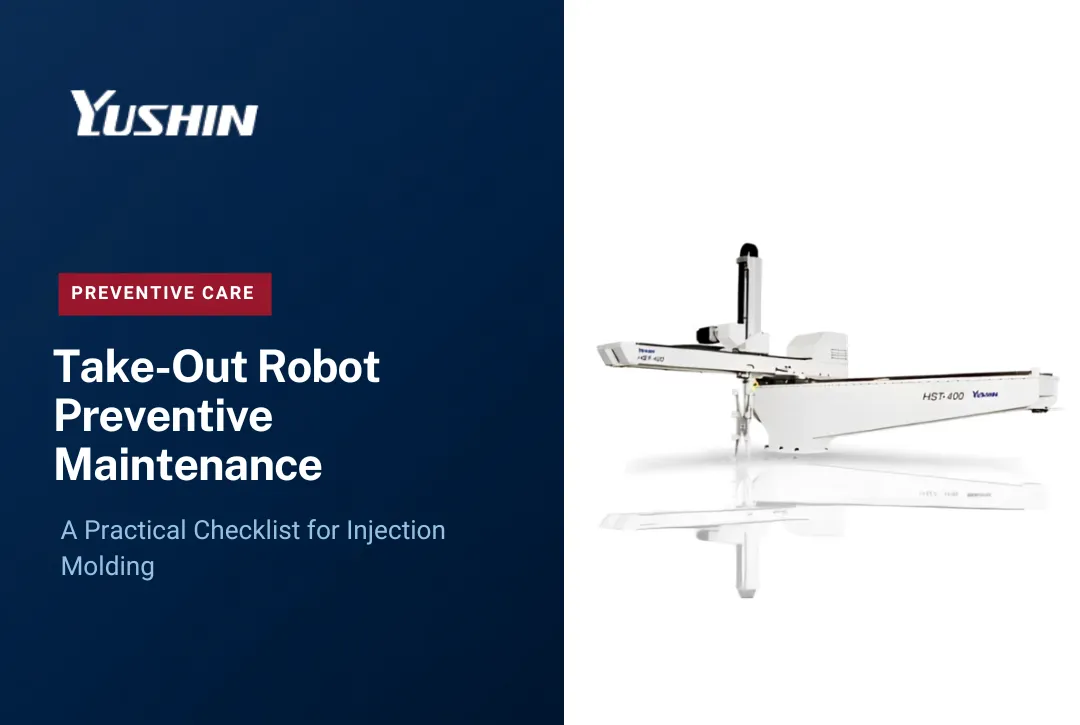
For fast-cycle packaging applications - thin-wall containers, closures, and similar high-cavitation parts - a standard robot is not the right tool. High-speed take-out robots like the HST Series are purpose-built for these conditions, with structural designs optimized for rigidity at high acceleration and deceleration rates. This is not a standard robot with larger motors; it is a fundamentally different mechanical architecture built around the demands of very short cycle times.
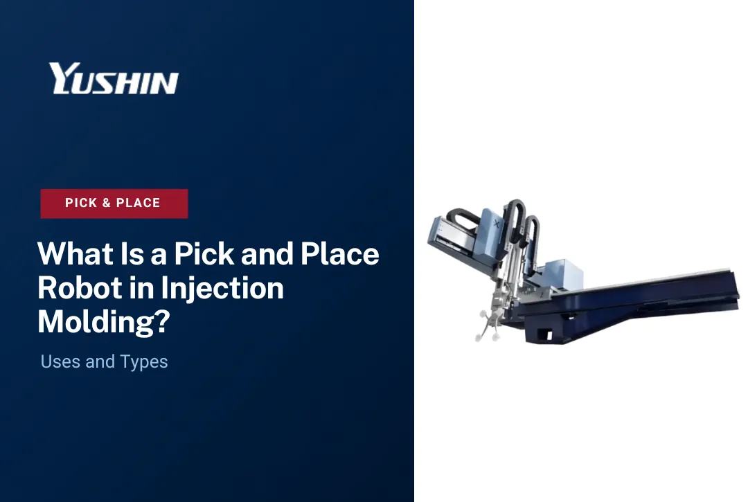
Where overhead clearance is limited - retrofit cells, low-ceiling facilities, or compact press configurations - side-entry robots enter from the side of the platen rather than overhead, preserving the machine footprint while still automating part extraction.
Sprue and Runner Removal
Not every molding cell uses a hot runner system. Cold runner and sprue-gated tooling produce runners and sprues that must be removed from the part or the mold area on every cycle.
A dedicated sprue picker handles this task. Sprue pickers are compact, swing-type or linear robots that reach into the mold, grip the sprue or runner, and remove it - either dropping it to a grinder below the press or depositing it separately for regrind.
This is a case where a separate, purpose-built device outperforms trying to do everything with the part take-out robot. The sprue picker operates on its own motion profile optimized for the small, fast movement required, leaving the primary take-out robot to focus on the part.
Insert Loading
Insert molding - placing metal inserts, bushings, or other components into the mold before the shot so they become encapsulated in the finished part - is a common process in automotive, electronics, and medical device molding.
Loading inserts by hand is slow and introduces placement variation that can cause defects or mold damage. A robot loading inserts does so at consistent position and orientation, every cycle, without fatigue.
Insert loading often requires the robot to rotate the insert to a precise angle for correct placement in the mold cavity. This is a genuine use case for NC servo wrist units, which add controlled rotational axes to the robot's wrist. The additional motion axes allow the robot to pick an insert from a feed system, rotate it to the required orientation, and place it accurately in the mold - tasks that a fixed-wrist robot cannot perform reliably. NC servo wrists are appropriate where the application actually requires this kind of controlled rotational motion; they are not a default add-on for every take-out application.
Part Orientation
After the robot extracts a part, the downstream process may require it in a specific orientation - label-side up for inspection, sprue-side down for degating, or a particular face forward for assembly. If the robot delivers the part in a random or inconsistent orientation, every subsequent operation degrades.
Part orientation can be addressed at the robot level - using servo wrist motion to rotate the part during transfer - or at the EOAT level, where the gripper geometry constrains how the part can be picked up in the first place. The right approach depends on the part geometry and the downstream requirement.
In-Mold Labeling
In-mold labeling (IML) places a pre-printed label inside the mold cavity before the shot. The injected plastic fuses around the label, producing a decorated part in a single cycle with no secondary labeling operation.
IML is demanding because label placement must be precise and the label must be positioned and held correctly before the mold closes. Side-entry robots are commonly used for high-speed IML applications because they can enter the mold area, place the label, and withdraw within a short mold-open window. The appropriate robot configuration still depends on the mold, label, cycle time, and overall cell layout.
Vision and Quality Inspection Integration
Camera-based inspection can be integrated directly into the take-out sequence. After the robot extracts the part and before it is deposited downstream, a vision system checks for defects, confirms dimensional features, reads part markings, or verifies color and surface condition.
The robot can present the part to the camera at a defined position and orientation consistently on each programmed inspection cycle. When the cell is configured for inspection of every presented part, defective parts can be identified and directed to a separate reject path before they reach downstream packaging or assembly. The inspection frequency and criteria depend on the application and vision-system configuration.
Vision integration requires that the robot's motion path include a presentation position with appropriate lighting and camera field of view. EOAT design and robot programming must account for this station.
Degating
Gate removal - separating the injection gate or sprue from the finished part - can be performed in the mold (hot knife, shear, or valve gate) or as a post-extraction operation. When degating happens outside the mold, the robot can be programmed to present the gate location to a fixed cutting station, or a separate degating fixture can be integrated into the robot's travel path.
Robot-performed degating is repeatable and consistent. Manual degating introduces cycle time variation and, with sharp tools, worker injury risk.
Assembly
Many injection molded products require combining two or more molded components immediately after molding - inserting a snap-fit component, pressing a bushing into a housing, or assembling a two-part hinge. Performing this operation directly in the molding cell, while the parts are still warm and dimensionally consistent, can reduce the need for secondary off-press operations.
A robot handling assembly tasks in the molding cell typically works with EOAT designed to grip multiple parts or to execute the assembly motion itself. For some secondary assembly operations, a collaborative robot may also be appropriate depending on payload, cycle time, workspace, and the application-level risk assessment. Yushin America offers the FANUC CRX collaborative robot for suitable collaborative applications.
Conveyor Transfer
After extraction and any in-cell operations, parts need to move to the next stage. A robot depositing parts onto a conveyor at a defined position, orientation, and rate provides consistent input to whatever comes next - inspection, assembly, decorating, or packaging.
The alternative - parts dropped by gravity into a bin or onto a chute - works for some applications but introduces orientation variation and the potential for part-on-part contact damage that is unacceptable for cosmetically sensitive or dimensionally critical parts.
Packing and Box Loading
Placing finished parts into shipping containers - trays, boxes, or bags - is repetitive physical work with no tolerance for inconsistency in automated downstream systems. A robot performing box loading places each part at a defined position in the container, building a consistent pack pattern that protects parts during shipping and allows automated unpacking at the customer's facility.
The EOAT for box loading is typically a gripper or vacuum tool matched to the part geometry. The robot program defines the pack pattern, and the system tracks fill count to trigger a container exchange when a box is full.
End-of-Line Palletizing
Packed boxes or trays move to palletizing as the final station before shipment. Palletizing is physically demanding and repetitive, and manual palletizing is a common source of musculoskeletal injuries in manufacturing facilities.
The PA Series palletizing robots from Yushin address end-of-line palletizing in injection molding environments. The compact, cantilever design is suited to the space constraints of a molding facility. The system builds pallet patterns from a defined configuration, handles the container exchange, and maintains consistent stack geometry for stretch-wrap and shipping.
Palletizing can present a clear automation case where repetitive manual lifting, staffing requirements, and consistent end-of-line throughput are meaningful operating concerns. Actual ROI depends on case volume, labor requirements, operating schedule, floor layout, and the system configuration.
Engineered Downstream Handling

Beyond the individual applications described above, a molding cell may require custom automation that connects multiple operations - a vision station feeding a sort-and-reject conveyor, a degating station integrated into the robot's travel path, or a system that coordinates the take-out robot with downstream assembly equipment.
Yushin's application engineering and systems integration capabilities address these scenarios. Engineered downstream automation moves beyond a single robot placed next to a press and into a coordinated production cell where each station hands off to the next with the precision the process requires.
Different Tasks Require Different Robots

One conclusion that runs through every application above: there is no universal robot for injection molding automation. Part take-out, insert loading, IML, and palletizing each have different motion requirements, payload needs, speed demands, and EOAT configurations. Treating all of these as interchangeable tasks for a single robot type produces compromised results.
The practical implication is that selecting automation for a molding cell starts with a clear description of each task, its timing requirements, the part, and what the downstream process needs - not with a robot model number.
Evaluating Your Molding Cell
A good starting point is to walk your production sequence and ask, for each operation:
- Is this task performed manually today, and is that the constraint on throughput or quality?
- Does the task require consistent timing, consistent placement, or consistent force?
- What does the downstream process receive, and does variation from this step cause problems there?
Operations where the answer to two or more of these questions is yes are usually strong automation candidates.
Conclusion
Robots can support many different tasks in plastics manufacturing, but the right automation depends on what the cell actually needs to accomplish. Part take-out, insert loading, orientation, inspection, downstream handling, and palletizing each place different demands on the robot and EOAT.
If you are evaluating which manual or inconsistent operations in your molding process are worth automating, contact Yushin America to review the application, part, EOAT, cycle requirements, and downstream process.
Frequently Asked Questions
What is the most common robotic application in injection molding?
Part take-out - removing the molded part from the open mold on each cycle - is the most widely used robotic application in injection molding. It directly supports consistent cycle time, protects parts from handling damage, and is the foundation for adding other downstream automation.
Do all injection molding robots need servo wrist units?
No. NC servo wrist units are appropriate for applications requiring controlled part rotation, such as insert loading, overmolding, angled placement, or downstream orientation changes. Standard take-out applications where the part is extracted and deposited in a consistent orientation do not require additional wrist axes.
What is the difference between a take-out robot and a sprue picker?
A take-out robot removes the molded part from the mold. A sprue picker is a separate, typically smaller device that removes the sprue or runner. Both can operate on the same press, serving distinct roles in the production cycle. Dedicated sprue pickers are faster and more compact for runner removal than asking the part take-out robot to handle both tasks.
Can vision inspection be integrated with injection molding robots?
Yes. A vision system can be integrated into the robot's motion path so that after part extraction, the robot presents the part to a camera at a defined position and orientation. Depending on the cell configuration, the system can inspect every presented part or operate according to another defined inspection strategy, with rejected parts directed away from normal downstream flow.
When does in-mold labeling require a side-entry robot?
IML requires placing a label in the mold cavity before the shot, which means the robot must enter and exit within the mold-open window of a fast-cycle press. Side-entry robots are designed for this motion profile. Overhead traverse robots entering from the top are not optimized for the speed or motion path that IML applications in high-cycle packaging require.
What should I evaluate before adding palletizing automation to a molding cell?
The key inputs are: box or tray dimensions, target pack pattern, line rate (boxes per hour), and available floor space. Pallet patterns must be defined in advance. If the facility runs multiple box sizes or pack configurations, that variability needs to be accounted for in the robot programming before the system is commissioned.